Positioning device and positioning navigation algorithm of robot based on infrared visual technology

A vision technology and a positioning device technology, which is applied in the field of positioning devices and positioning and navigation algorithms, can solve the problems of slow recognition speed, low recognition rate, and greater influence of image afterimages

Inactive Publication Date: 2017-02-22
KUSN TAMI ROBOT
View PDF8 Cites 5 Cited by
  • Summary
  • Abstract
  • Description
  • Claims
  • Application Information

AI Technical Summary

Problems solved by technology

[0002] Infrared technology positioning and navigation is that the infrared lens has the characteristics of thermal imaging, long irradiation distance, and clear image quality, so it is often used in high-performance image segmentation, detection and recognition. However, the infrared lens still has a lot of defects, which leads to the current Infrared technology positioning and navigation algorithms are greatly affected by ambient light and afterimages when moving. Although there are many processing algorithms, the recognition speed is slow, the recognition rate is low, and it relies too much on the computing power of hardware devices; the existing technology has not yet solved such problems.

Method used


Image

  • Positioning device and positioning navigation algorithm of robot based on infrared visual technology
  • Positioning device and positioning navigation algorithm of robot based on infrared visual technology
  • Positioning device and positioning navigation algorithm of robot based on infrared visual technology

Examples


Embodiment Construction

[0031] The present invention will be specifically introduced below in conjunction with the accompanying drawings and specific embodiments.

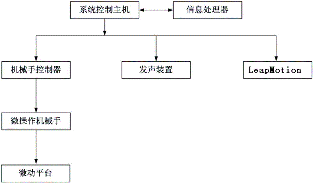
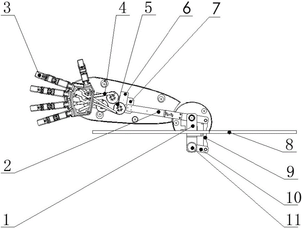
[0032] A positioning device for a robot based on infrared vision technology, comprising: infrared image acquisition equipment, a positioning control module that receives information from the infrared image acquisition equipment; the infrared image acquisition equipment consists of: an infrared signal lamp, an infrared camera, located on the infrared camera The positioning star mark 1 of infrared reflection; the infrared camera is composed of: an infrared lens 2, an infrared light-emitting tube 3 arranged around the infrared lens 2, and an infrared camera circuit board 4 arranged under the infrared light-emitting tube 3 . It should be noted that the positioning control module is realized based on the following hardware conditions, operating system: Microsoft Windows 7 Professional SP1, processor: Intel(R) Celeron(R) CPU N3150 @ 1.60GHz, mem...


PUM


Abstract

The invention discloses a positioning device and positioning navigation algorithm of a robot based on the infrared visual technology. The positioning device comprises infrared image collecting equipment and a positioning control module for receiving information of the infrared image collecting equipment. The infrared image collecting equipment is composed of an infrared signal lamp, an infrared camera and a positioning star target located on the infrared camera and used for reflecting infrared rays. The infrared camera is provided with an infrared lens, an infrared light-emitting tube arranged around the infrared lens, and an infrared camera circuit board arranged below the infrared light-emitting tube. Overexposure of the camera on infrared light is reduced, and the influence of ambient light and movement on photo taking is reduced; by means of correction of parameters of the infrared collecting equipment, the influence of the ambient light can be effectively reduced; due to the fact that the algorithm efficiency of a visual processing system is improved, the influence of residual shadows generated during movement can be effectively reduced. By means of the algorithm, the actual errors of a body reaching a target point during navigation are reduced within the acceptable range.

Description

technical field [0001] A positioning device and its positioning and navigation algorithm, in particular a positioning device and its positioning and navigation algorithm for a robot based on infrared vision technology. Background technique [0002] Infrared technology positioning and navigation is that the infrared lens has the characteristics of thermal imaging, long irradiation distance, and clear image quality, so it is often used in high-performance image segmentation, detection and recognition. However, the infrared lens still has a lot of defects, which leads to the current Infrared technology positioning and navigation algorithms are greatly affected by ambient light and afterimages when moving. Although there are many processing algorithms, the recognition speed is slow, the recognition rate is low, and it relies too much on the computing power of hardware devices; the existing technology has not yet solved such problems. Contents of the invention [0003] In order...

Claims


Application Information

Patent Timeline
Patent Type & Authority Applications(China)
IPC IPC(8): G01C11/02G01C21/00G06T7/33
CPCG01C11/02G01C21/00
Inventor 张鑫吴季泳郭锐苗靖
Owner KUSN TAMI ROBOT
Why Eureka
Try Eureka