Clamping device for rodlike sample long-time creep test

A creep test and clamping device technology, applied in the direction of measuring devices, instruments, scientific instruments, etc., can solve the problems that affect the accuracy of the test results, cannot be reused, and increase the cost of the test, so as to ensure the coaxiality of the test and ensure the Blessing and action effects, simple structure effects

Pending Publication Date: 2017-02-22
HUANENG POWER INT INC +1
View PDF6 Cites 2 Cited by
  • Summary
  • Abstract
  • Description
  • Claims
  • Application Information

AI Technical Summary

Problems solved by technology

At present, rod-shaped persistent creep samples are usually clamped and fixed by clamps with thread structure. Although good coaxiality can be guaranteed, it is inconvenient to disassemble, especially after long-term service at high temperature and high pressure, sintering and oxidation will occur. In serious cases, only by destroying the clamping device can the clamp and the sample be removed after the test. This will not only damage the sample during the sample taking process, but also cause irreversible damage to the clamping device, making It cannot be reused, greatly increasing the cost of testing
In addition, this type of experiment has high requirements on coaxiality. Due to various factors such as the design, processing, assembly and use of the upper and lower sample clamping devices of the testing machine, there is inevitably a coaxiality positioning error.
Influenced by the positioning error of coaxiality, in the durability / creep test of materials, additional stresses will be generated due to bending when the test bears normal stress, such as bending normal stress and bending shear stress, etc., thus affecting the accuracy of test results

Method used


Image

  • Clamping device for rodlike sample long-time creep test
  • Clamping device for rodlike sample long-time creep test
  • Clamping device for rodlike sample long-time creep test

Examples


Embodiment Construction

[0020] The present invention will be further described in detail below in conjunction with specific embodiments, which are explanations of the present invention rather than limitations.

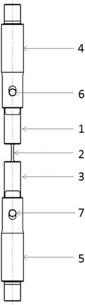
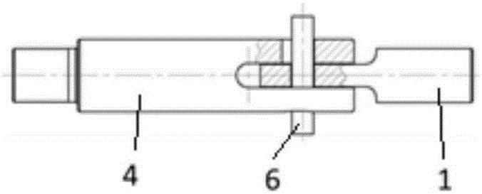
[0021] A clamping device for a rod-shaped sample durable creep test of the present invention, such as figure 1 As shown, it includes an upper pull rod 4, a lower pull rod 5, an upper clamp 1, a lower clamp 3, an upper positioning pin 6 and a lower positioning pin 7, and the rod-shaped sample 2 to be tested is connected between the upper clamp 1 and the lower clamp 3, and the upper clamp 1 The pull rod 4 and the lower rod 5 are symmetrically arranged, the upper clamp 1 and the lower clamp 3 are symmetrically arranged, and the upper positioning pin 6 and the lower positioning pin 7 are symmetrically arranged.

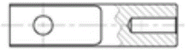
[0022] Wherein, the upper end of the upper fixture 1 is a plate-shaped structure, which is connected with the upper fixture 1 through the upper positioning pin 6; the lower end of the up...


PUM


Abstract

The invention provides a clamping device for a rodlike sample long-time creep test. The clamping device includes clamping units symmetrically fixed to the two ends of a to-be-tested rodlike sample; each clamping unit includes a jig and a pull rod; one end of each jip is fixedly connected with the to-be-tested rodlike sample by threads, the other end of each jip is connected with one end of the corresponding pull rod by a pin, and the other end of each pull rod is connected with a long-time creep tester main body. Threaded connection ensures the coaxiality of the to-be-tested rodlike sample, the existing to-be-tested rodlike sample does not require structural change and can be directly used, and symmetric arrangement also ensures the use flexibility of the to-be-tested rodlike sample; at the same time, through the connection of the jigs and the pull rods by the pins, rapid and flexible clamping can be conducted before and after the test. The clamping device is simple in structure, and the test can be guaranteed to be carried out smoothly on the premise that the coaxiality is ensured; after the test is completed, the upper jig and the upper pull rod are separated smoothly, the lower jig and the lower pull rod are separated smoothly, and the disassembly inconvenience problem is solved.

Description

technical field [0001] The invention relates to a clamping tool for a mechanical performance test, in particular to a clamping device for a rod-shaped sample durable creep test. Background technique [0002] Endurance / creep test is a kind of high-temperature mechanical performance test to measure the fracture resistance / deformation resistance of materials under high temperature and long-term load. For many high-temperature parts, such as boiler overheating and reheater tubes, etc., not only need good short-term tensile properties, excellent oxidation resistance, but also need to bear a certain stress during service, which requires good High temperature durability / creep properties. In order to obtain the durability / creep properties of the material, long-term experiments must be carried out. The heating furnace of the endurance / creep testing machine is generally long, and except for the sample to be tested, most of the entire clamping device is in a state of high temperature...

Claims


Application Information

Patent Timeline
Patent Type & Authority Applications(China)
IPC IPC(8): G01N3/04
CPCG01N3/04G01N2203/0071G01N2203/0266G01N2203/0252G01N2203/0423G01N2203/0016G01N2203/0003
Inventor 党莹樱赵新宝张洋洋刘冲尹宏飞袁勇
Owner HUANENG POWER INT INC
Why Eureka
Try Eureka