Angle servo monitoring system and method

A detection system and angle technology, applied in radio wave measurement systems, instruments, etc., can solve the problems of not adapting to efficient combat needs, endangering human health, low degree of automation, etc., to achieve full automation of test work, avoid damage, and solve automation. low level effect

Active Publication Date: 2017-02-22
CHENGDU RONG WEI ELECTRONICS TECH DEV CO
View PDF4 Cites 2 Cited by
  • Summary
  • Abstract
  • Description
  • Claims
  • Application Information

AI Technical Summary

Problems solved by technology

[0003] The purpose of the present invention is to provide an angle follow-up monitoring system and method for the deficiencies of the prior art. health problems

Method used


Image

  • Angle servo monitoring system and method
  • Angle servo monitoring system and method
  • Angle servo monitoring system and method

Examples


Embodiment Construction

[0030] In order to make the purpose, technical solution and advantages of the present application clearer, the present application will be further described in detail below in conjunction with the accompanying drawings and specific embodiments.

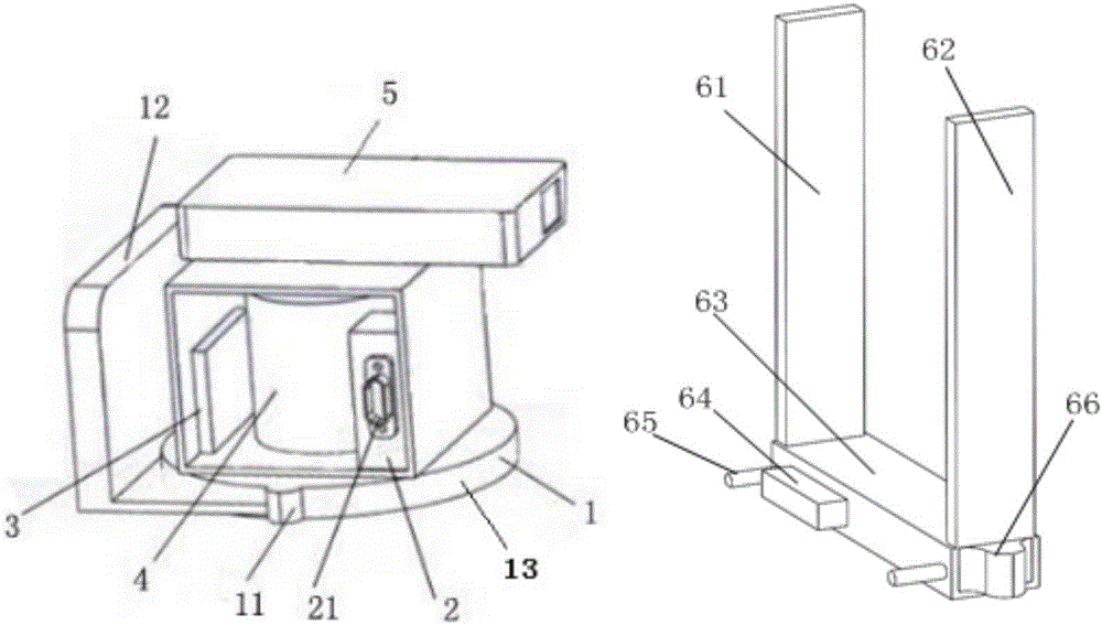
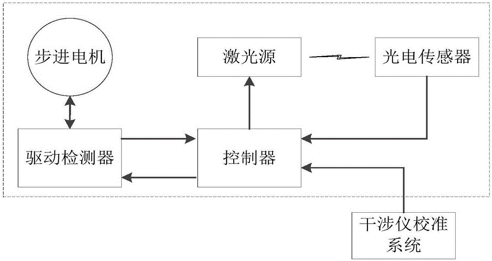
[0031] This application provides an angle follow-up measurement system, such as Figure 1-2 shown, including:

[0032] The laser source 5 is used to generate a laser signal;

[0033] A stepper motor 4, the output shaft of which is connected to the laser source 5, is used to drive the laser source 5 to rotate in a horizontal circle;

[0034] Drive the detector 3, drive the stepper motor 4 to rotate according to the received pulse, detect and control the rotation angle and speed of the stepper motor 4;

[0035] A photoelectric sensor for receiving a laser signal and converting the laser signal into an electrical signal for output;

[0036] The controller 2 is connected to the laser source 5, the drive detector 3 and the photoelectric...


PUM


Abstract

The invention provides an angle servo monitoring system and method. Automatic measurement of deviation angle is implemented by matching a controller, a drive detector, a stepping motor, a laser source and a photoelectric sensor, function testing can be finished through one click, and individual operation is facilitated; the problems of low automation level and complex testing process are solved, and the efficient troop operation can be met; by the end of each measurement, laser beam emitted by the laser source is aligned with the position between a first array and a second array through rotation, algorithm is in the status of servo monitoring, when one array receives a laser signal, the system is triggered to perform angle measurement, the angle servo measurement is implemented, full automation of testing is realized, and the testing efficiency is improved; the controller is provided with a system remote control port, the remote control of the system can be implemented, and the damage of testers by high-power microwave radiation is avoided.

Description

technical field [0001] The invention relates to the technical field of angle measurement, in particular to an angle follow-up monitoring system and method. Background technique [0002] The military radar interferometer direction-finding antenna needs to determine the offset angle between the normal plane of the interferometer antenna and a certain direction in real time when performing periodic direction-finding calibration. The traditional method is to use a total station to manually determine the azimuth angle, which is complicated to operate. The degree of automation is low, it is difficult for soldiers to use, and it cannot be integrated into the interferometer calibration system. The test work takes a long time and does not meet the current efficient combat needs. At the same time, high-power microwave radiation will damage the health of test personnel. Contents of the invention [0003] The purpose of the present invention is to provide an angle follow-up monitoring...

Claims


Application Information

Patent Timeline
Patent Type & Authority Applications(China)
IPC IPC(8): G01S7/40
CPCG01S7/4026
Inventor 吴昊何斌陈刚刘磊张永清王倩陈柳州
Owner CHENGDU RONG WEI ELECTRONICS TECH DEV CO
Why Eureka
Try Eureka