
Particle swarm optimization based control method and device of photovoltaic maximum power point tracking

A technology of maximum power point and particle swarm optimization, applied in the field of solar photovoltaic power generation, which can solve the problems of falling into local extreme points, slow search speed, and many random parameters.

Inactive Publication Date: 2017-02-22
BEIJING INFORMATION SCI & TECH UNIV
View PDF5 Cites 35 Cited by
  • Summary
  • Abstract
  • Description
  • Claims
  • Application Information

AI Technical Summary

Problems solved by technology

[0007] The invention provides a control method and device for photovoltaic maximum power point tracking based on particle swarm optimization, which solves the technical problems in the prior art that the search speed is slow, there are many random parameters, and there is a possibility of falling into a local extreme point

Method used


Image

  • Particle swarm optimization based control method and device of photovoltaic maximum power point tracking
  • Particle swarm optimization based control method and device of photovoltaic maximum power point tracking
  • Particle swarm optimization based control method and device of photovoltaic maximum power point tracking

Examples


Embodiment Construction

[0034] In order to make the above objects, features and advantages of the present invention more comprehensible, the present invention will be further described in detail below in conjunction with the accompanying drawings and specific embodiments.

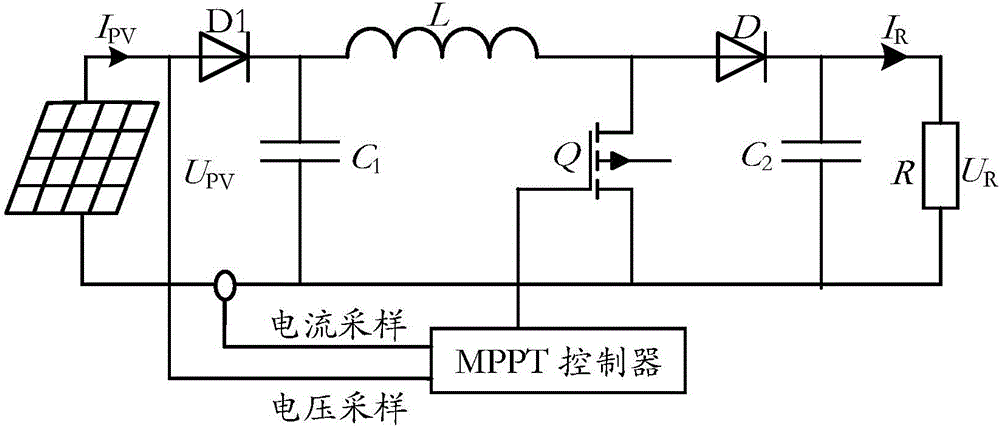
[0035] Such as figure 1 As shown, it is a schematic diagram of the circuit structure of the photovoltaic maximum power tracking (Maximum Power Point Tracking, MPPT) system. The MPPT controller samples the output current I of the photovoltaic array PV and the output voltage U PV , output duty cycle control signal to control the photovoltaic array to work stably at the maximum power point. Depend on figure 1 The input-output relationship of the Boost converter in

[0036] Equivalent voltage of Boost circuit Then the duty cycle can be expressed as Correspondingly, the maximum duty cycle Minimum duty cycle R is the load resistance. It can be seen that by adjusting the duty ratio d, the equivalent resistance of the Boost cir...


PUM


Abstract

The invention relates to the field of solar photovoltaic power generation and discloses a particle swarm optimization based control method and device of photovoltaic maximum power point tracking. A duty ratio of a converter is used as particles, the particles are initialized and uniformly dispersed at possible extreme value points, inertia weight and learning factor are adjusted linearly, an anti-tangent function is introduced to modify conventional particle swarm speed updating, and speed of each particle is limited solely. Convergence rate of a particle swarm algorithm is increased, oscillation during tracking is reduced, and new maximum power points can be quickly tracked during shadow changing.

Description

technical field [0001] The invention relates to the field of solar photovoltaic power generation, in particular to a control method and device for photovoltaic maximum power point tracking based on particle swarm optimization. Background technique [0002] Under partial shading conditions, the P-U curve of the photovoltaic array changes from a single peak to multiple peaks, and the traditional maximum power point tracking method can only track one of the local extreme points and fails. Partial shadows may occur at any time, which greatly reduces the system efficiency. Therefore, an effective global MPPT method under multi-peak conditions must be proposed. [0003] To solve this problem, in the prior art [0004] 1. The parallel power compensation method is used to eliminate the multi-peak phenomenon by adding power compensation units. This method is simple and feasible, but the system structure is complex and the cost is high. [0005] 2. The composite MPPT algorithm is ad...

Claims


Application Information

Patent Timeline
Patent Type & Authority Applications(China)
IPC IPC(8): G05F1/67
CPCG05F1/67Y02E10/56
Inventor 张巧杰王凯丽
Owner BEIJING INFORMATION SCI & TECH UNIV
Learn More