Capacitive touch screen, capacitive touch screen bending judgment method and displaying device

一种电容式触摸屏、弯曲的技术,应用在电数字数据处理、仪器、计算等方向,能够解决产品成本与可靠度影响等问题

Active Publication Date: 2017-02-22
BOE TECH GRP CO LTD
View PDF7 Cites 34 Cited by
  • Summary
  • Abstract
  • Description
  • Claims
  • Application Information

AI Technical Summary

Problems solved by technology

At present, the curved body can be used to input commands to achieve a new experience of the human-machine interface, but the existing touch screen needs to add additional sensing elements to judge the bending state of the screen, which will affect the cost and reliability of the product.

Method used


Image

  • Capacitive touch screen, capacitive touch screen bending judgment method and displaying device
  • Capacitive touch screen, capacitive touch screen bending judgment method and displaying device
  • Capacitive touch screen, capacitive touch screen bending judgment method and displaying device

Examples


Embodiment 1

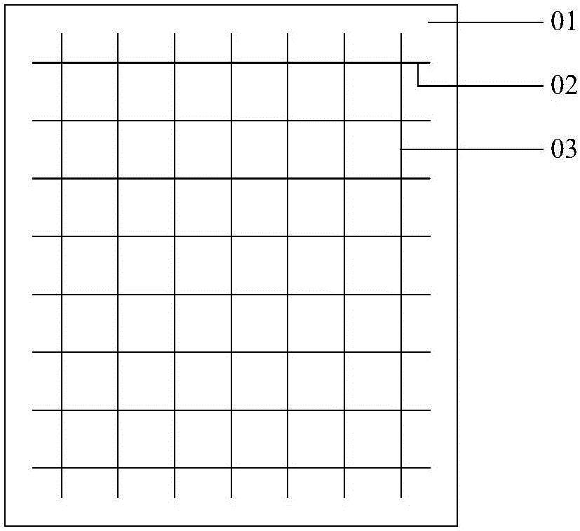
[0081] During specific implementation, in the above-mentioned capacitive touch screen provided by the embodiment of the present invention, as Figure 7 As shown, when the orthographic projection of the touch sensing electrodes 02 and touch driving electrodes 03 on the base substrate 01 is in a grid shape, and when the touch sensing electrodes 02 and the touch driving electrodes 03 are arranged on the same layer, and the touch The distance between the control sensing electrode 02 and the touch driving electrode 03 is d, such as Figure 8a and Figure 8b As shown, when the capacitive touch screen is bent, the distance d between the touch sensing electrode 02 and the touch driving electrode 03 will change. For example Figure 8a As shown, when the capacitive touch screen is bent toward the side of the base substrate 01 facing the touch sensing electrode 02, the distance d between the touch sensing electrode 02 and the touch driving electrode 03 becomes smaller, and the touch se...

Embodiment 2

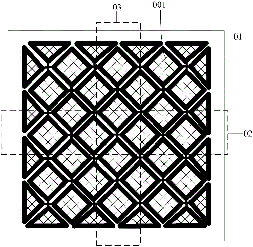
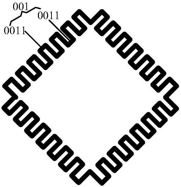
[0083] During specific implementation, in the above-mentioned capacitive touch screen provided by the embodiment of the present invention, as Figure 9 and Figure 10 As shown, the touch driving electrode 03 is located between the touch sensing electrode 02 and the base substrate 01 , and an insulating layer 04 is provided between the touch sensing electrode 02 and the touch driving electrode 03 . Such as Figure 9 As shown, when the orthographic projection of the touch sensing electrode 02 and the touch driving electrode 03 on the base substrate 01 is composed of a plurality of line segments with different extending directions connected sequentially, or as shown in FIG. Figure 10 As shown, when the touch sensing electrode 02 is composed of the first sub-electrode 021 and the second sub-electrode 022 arranged in different layers, the touch driving electrode 03 is composed of the third sub-electrode (not shown in the figure) and the second sub-electrode arranged in different ...


PUM


Abstract

The invention discloses a capacitive touch screen, a capacitive touch screen bending judgment method and a displaying device. The capacitive touch screen comprises a substrate baseplate, touch induced electrodes, touch driving electrodes and a touch chip. When the touch screen bends, most of the coupling capacitance values generated from the touch induced electrodes and the touch driving electrodes change sharply compared with those generated when the touch screen does not bend. Therefore, by inflicting driving signals on the touch driving electrodes, capacitance values of various touch induced electrodes are then detected; when there are changes of capacitance values in adjacent touch induced electrodes which are more than or equal to preset touch induced electrodes, and when the capacitance differences among the touch induced electrodes which have changes in capacitance values are smaller than preset values, the bending state of the capacitive touch screen can be determined according to the capacitance value changing information of the touch induced electrodes. The capacitive touch screen can judge the bending state of the screen without adding a sensing element, thus lowering cost in products and having no influence on reliability of the products.

Description

technical field [0001] The invention relates to a display device, in particular to a capacitive touch screen, a bending judgment method thereof and a display device. Background technique [0002] The touch screen is an input device that significantly improves the man-machine interface, and has the advantages of intuition, simplicity and speed. Touch screens have been widely used in many electronic products, such as mobile phones, PADs, multimedia, and public information inquiry systems. There are four main types of touch screens, including resistive, capacitive, infrared and surface acoustic wave touch screens. Among them, the capacitive touch screen has excellent performance, for example, there is no problem of mechanical movement and wear in the screen, and it has a simple structure, high light transmittance, good linearity, dustproof, fireproof, and scratch-resistant, even in the harshest environment. With stable performance, etc., it has become the mainstream of the ma...

Claims


Application Information

Patent Timeline
Patent Type & Authority Applications(China)
IPC IPC(8): G06F3/044
CPCG06F3/044G06F2203/04102G06F2203/04104G06F3/0416G06F3/0443G06F3/0445G06F3/0446G06F3/0448G02F1/13338G02F1/1343
Inventor 王明玺史世明毛雪蔡宝鸣
Owner BOE TECH GRP CO LTD
Why Eureka
Try Eureka