
Cervical vertebra motion degree and motion axial line position determining method, system and device

A technology for determining the method and degree of activity, applied in image data processing, instruments, calculations, etc., can solve problems such as low accuracy, inability to locate the cervical spine activity axis, cumbersome measurement process, etc., to achieve accurate spatial position, spatial positioning, and measurement. Simple process effect

Pending Publication Date: 2017-02-22
BEIJING INSTITUTE OF TECHNOLOGYGY
View PDF3 Cites 15 Cited by
  • Summary
  • Abstract
  • Description
  • Claims
  • Application Information

AI Technical Summary

Problems solved by technology

However, the measurement methods currently used are cumbersome, have low accuracy, and cannot locate the position of the axis of cervical motion

Method used


Image

  • Cervical vertebra motion degree and motion axial line position determining method, system and device
  • Cervical vertebra motion degree and motion axial line position determining method, system and device
  • Cervical vertebra motion degree and motion axial line position determining method, system and device

Examples


specific Embodiment

[0094] A specific embodiment of the present invention is as follows:

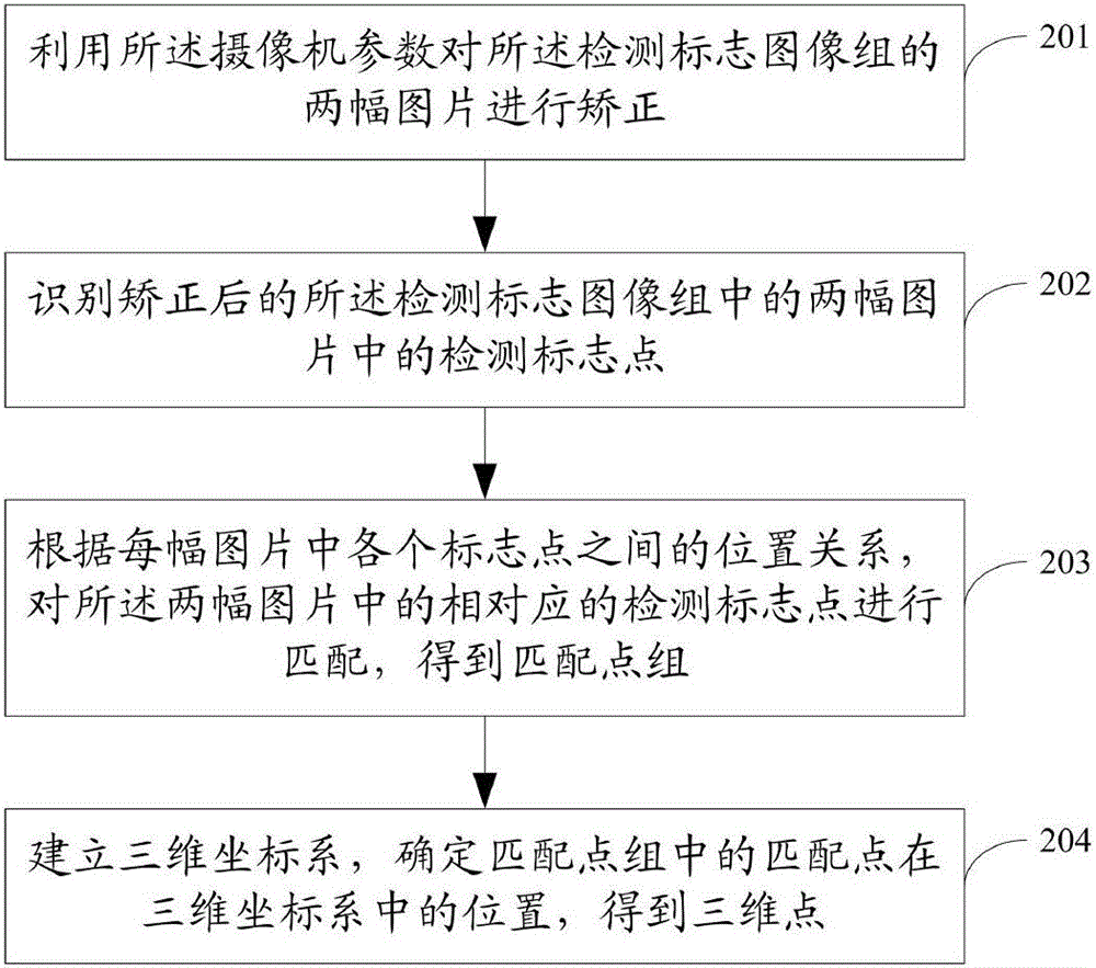
[0095] The binocular vision camera uses two CCD cameras, both with 12 million pixels, and a camera with a maximum resolution of 800×600ppi. Two CCD cameras are set in parallel. The binocular vision camera needs to be calibrated by computer before use. Through calibration, the internal reference matrices M1 and M2 of the two cameras, the distortion coefficient matrices D1 and D2 of the two cameras, and the rotation matrices R1 and R2 required for the two cameras to achieve parallelism respectively are obtained. After the binocular vision camera is calibrated, the relative position and horizontal height of the two CCD cameras are fixed.


PUM


Abstract

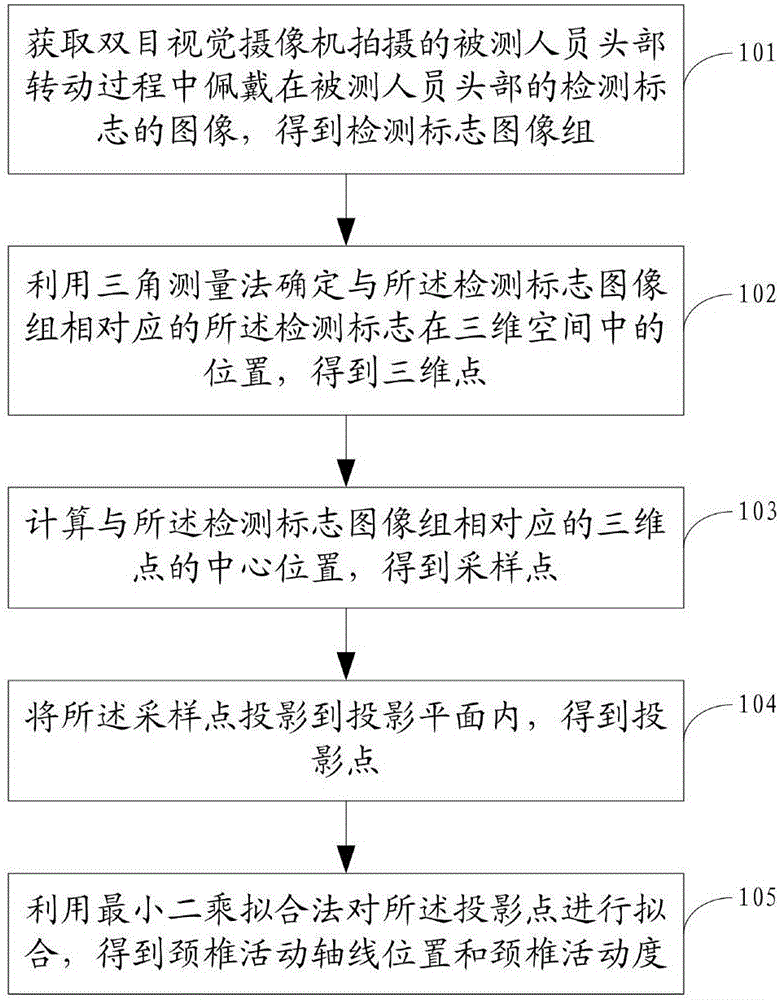
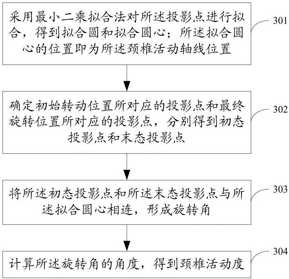
The invention discloses a cervical vertebra motion degree and motion axial line position determining method, system and device. The method comprises the following steps of obtaining an image, of a detection mark worn on the head of a tested person in the head rotating process of the tested person, shot by binocular vision cameras, and obtaining a detection mark image group, wherein the binocular vision cameras are two cameras in parallel arrangement; determining the position of the detection mark corresponding to the detection mark image group in a three-dimensional space by a triangular measuring method to obtain a three-dimensional point; calculating a center position of the three-dimensional point corresponding to the detection mark image group to obtain a sampling point; projecting the sampling point into a projection plane to obtain a projection point; fitting the projection point by a least-square fitting method to obtain a cervical vertebra motion axial line position and a cervical vertebra motion degree. The method, the system and the device provided by the invention have the advantages that the determination of the cervical vertebra motion axial line position can be realized; the detection process is simplified; the cervical vertebra motion degree can be accurately determined.

Description

technical field [0001] The invention relates to the field of machine vision, in particular to a method, system and device for determining the range of motion of the cervical spine and the position of the motion axis. Background technique [0002] Accurately and quickly measuring the range of motion of the cervical spine and obtaining the position of the axis of motion of the cervical spine has always been a thorny issue in basic medicine and clinical medicine. It is also important to obtain the position of the axis of motion of the cervical spine while determining the range of motion of the cervical spine. The currently used methods of measuring the range of motion of the cervical spine include measuring the range of motion of the cervical spine, measuring with an electric goniometer, measuring with a spinal activity analyzer, measuring with a modified square disk goniometer, measuring cervical spine dynamics, tape measure and visual inspection. Dozens of others. However, t...

Claims


Application Information

Patent Timeline
Patent Type & Authority Applications(China)
IPC IPC(8): G06T7/80G06T7/70
CPCG06T2207/20088G06T2207/10004G06T2207/30008
Inventor 赖汝和海渔李健陈振刘向东
Owner BEIJING INSTITUTE OF TECHNOLOGYGY
Learn More