Directional motion control method of semiconductor micro-nano particles

A technology of micro-nano particles and directional movement, applied in radiation/particle processing, manipulation of neutral particles by radiation pressure, nuclear engineering, etc., to achieve high control precision, wide application range, and simple operation

Active Publication Date: 2018-08-07
WUHAN UNIV OF TECH
View PDF6 Cites 0 Cited by
  • Summary
  • Abstract
  • Description
  • Claims
  • Application Information

AI Technical Summary

Problems solved by technology

But even with these external field control methods, it is still a bottleneck in this field to achieve real-time high-precision control of the motion state and direction of the micro-nano motor

Method used


Image

  • Directional motion control method of semiconductor micro-nano particles
  • Directional motion control method of semiconductor micro-nano particles
  • Directional motion control method of semiconductor micro-nano particles

Examples


Embodiment 1

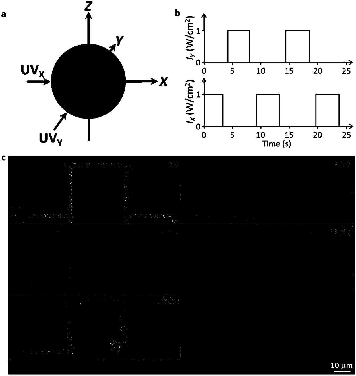
[0038] A control method for optically controlling the movement of titanium dioxide micro / nano microspheres, which comprises the following steps: dispersing titanium dioxide microspheres into a certain concentration of hydrogen peroxide fuel (0.000001-1wt.%), according to figure 1 Build an illumination platform, set the angle between the light and the horizontal plane to be θ (0°≤0≤90°), and set the output power of the light source to 1W, then the negative phototaxis motion of titanium dioxide microspheres can be obtained. Among them, (a) is a schematic diagram of ultraviolet light irradiating semiconductor micro-nano particles. UV X and UV Y are the projections of light X and Y on the X-Y plane, respectively. (b) Schematic diagram of the switching cycle of light sources X and Y. (c) is a time series photograph of a typical titanium dioxide spherical micro-particle moving in 0.001wt.% hydrogen peroxide solution, and the dotted line indicates the preset moving route of the ti...

Embodiment 2

[0045] An ultraviolet light emitting device was built according to the conditions in Example 1, and the movement properties of titanium dioxide microspheres with particle diameters of 400 nm, 1.2 μm and 3.5 μm were respectively tested. Under the condition of hydrogen peroxide concentration of 0.001wt%, particles with a particle size of 400nm and 3.5μm only exhibited random Brownian motion, indicating that the product concentration difference between the illuminated side and the backlit side of the particle cannot drive the particle to move, such as Figure 4 shown. When the concentration distribution of hydrogen peroxide increased to 0.1wt% and 0.66wt%, the particles with particle size of 400nm and 3.5μm began to show negative phototaxis motion.

Embodiment 3

[0047] Build an ultraviolet light emitting device according to the conditions in Example 1, adjust the value of the included angle θ of the ultraviolet light source on the horizontal plane, use ultraviolet light with a power of 1W to irradiate the particles, and find that the movement speed of the particles changes with the change of the included angle θ, as shown in Figure 5 As shown, when θ=0°, the particle loses the ability of directional movement, and only shows random movement without direction. The reason for this phenomenon is that the product concentration distribution near the particle is evenly distributed around the particle under this lighting condition.


PUM


Abstract

The invention discloses a semiconductor micro-nano particle oriented motion control method. Semiconductor micro-nano particles are dispersed into a hydrogen peroxide solution or pure water; and the semiconductor micro-nano particles are irradiated by use of a light source, the surfaces of the particles asymmetrically generate photocatalysis reaction, and thus oriented motion of the particles is realized. The semiconductor micro-nano particles are irradiated by use of parallel light sources, and motion along the same direction is realized. Through control of light source intensity or the concentration of the hydrogen peroxide solution, the motion rate is controlled. The particles are irradiated from a certain angle by use of light beams with specific wavelengths, the semiconductor micro-nano particles are irradiated by the light source to excite electron hole pairs (the forbidden bandwidth of a semiconductor material ranges from 1 to 4.2 electron volts), electron holes participate in chemical reaction of the surfaces, products are generated in an orientated mode, and a local product concentration difference is constructed; and the local product concentration difference excites osmotic pressure flows around the particles and enables the particles to move towards a positive phototaxis or negative phototaxis direction so as to realize oriented motion of the particles.

Description

technical field [0001] The invention belongs to the technical field of micro-nano motors, and relates to a method for controlling the directional movement of semiconductor micro-nano particles. Background technique [0002] Artificial micro-nano motors are an important part of micro-nano machines. They can perform various tasks in liquid environments, such as drug delivery, cell separation, photolithography or environmental governance (Chem. Rev. 2014, 114, 6285; ACS Applied Materials & Interfaces 2014, 6, 9897; Nat Commun 2014, 5.). In order to realize the self-driving of micro-nano motors, it is necessary to build asymmetric fields around them, including concentration gradient fields, asymmetric bubble release, etc. In order to construct these asymmetric fields, complex micro-nano structures are often required, such as double-sided god nanorods, microspheres, microtubes, etc. (Chem. Rev. 2015, 115, 8704.). These complex micro-nanostructures are often difficult to obtain....

Claims


Application Information

Patent Timeline
Patent Type & Authority Patents(China)
IPC IPC(8): G21K1/00
CPCG21K1/006
Inventor 官建国陈传瑞牟方志
Owner WUHAN UNIV OF TECH
Why Eureka
Try Eureka