
A Coaxial Spin Injection Device

A spin injection, coaxial technology, applied in semiconductor devices, electrical components, circuits, etc., can solve the problem of holes, reduce the efficiency of spin injection, and the effective contact area between the spin injection electrode and the channel is not controllable. Improves efficiency, improves controllability and reliability, reduces effects of electron scattering problems

Active Publication Date: 2019-04-05
BEIHANG UNIV
View PDF4 Cites 0 Cited by
  • Summary
  • Abstract
  • Description
  • Claims
  • Application Information

AI Technical Summary

Problems solved by technology

[0004] In traditional spin injection devices, due to the direct contact between the spin channel material (such as graphene, carbon nanotubes, etc.) and the substrate at the spin injection electrode, it causes additional electron scattering problems and reduces the spin injection. efficiency
At the same time, for the case of one-dimensional materials such as carbon nanotubes, due to their unique hollow cylindrical topological structure, holes are easily generated on the contact surface between the spin injection electrode and the carbon nanotube, resulting in the effective contact area between the spin injection electrode and the channel. uncontrollable
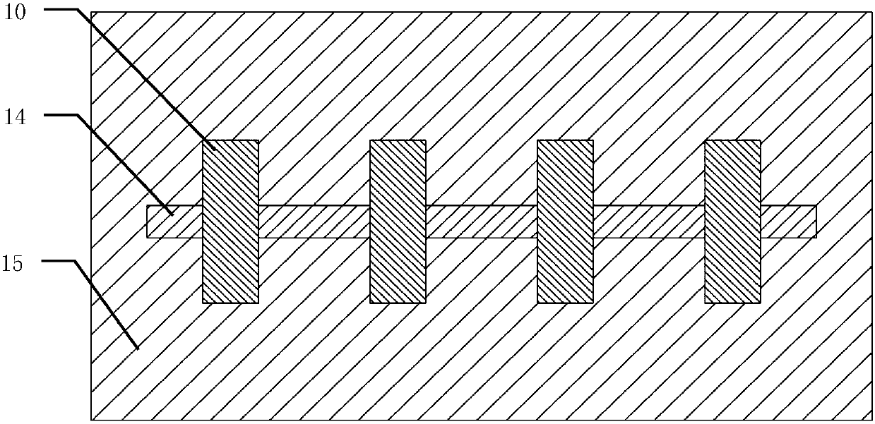
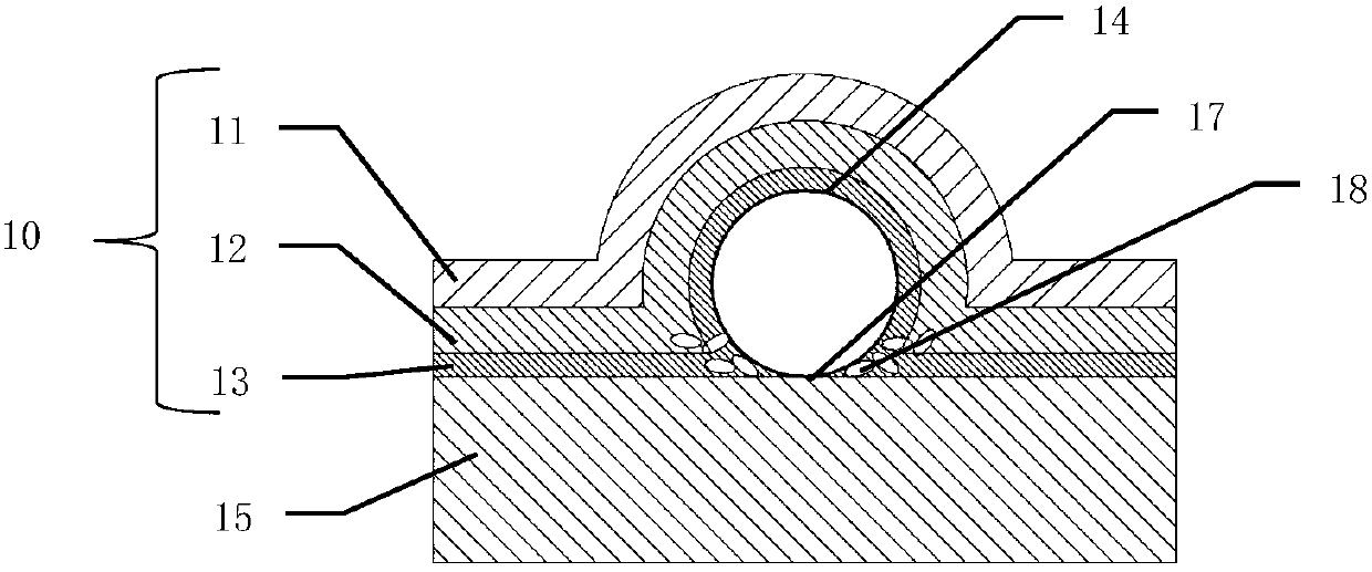
[0005] In order to solve the above problems, the present invention proposes a coaxial spin injection device. The spin injection electrode of the device coaxially surrounds the one-dimensional spin channel, which can effectively solve the problem caused by the contact between the one-dimensional spin channel and the substrate. The scattering problem of the spin injection electrode / one-dimensional spin channel interface is also avoided, and the spin injection efficiency is effectively improved.

Method used


Image

  • A Coaxial Spin Injection Device
  • A Coaxial Spin Injection Device
  • A Coaxial Spin Injection Device

Examples


specific Embodiment approach

[0041] In the embodiment of the present invention, we use coaxial spin injection electrodes to solve the above two problems. The specific implementation is as follows:

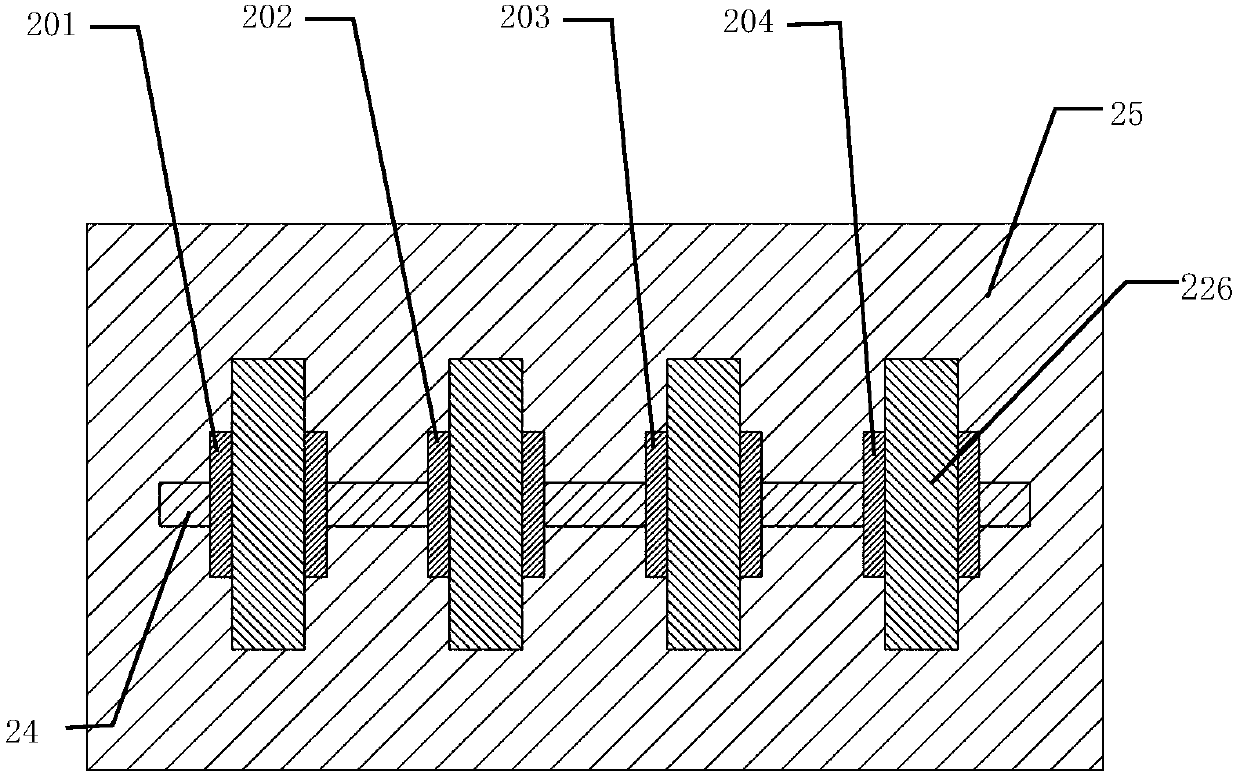
[0042] Figure (2) is a top view of the coaxial spin injection device, and Figure 2(b) is a cross-sectional view of Figure 2(a). As shown in FIG. 2( a ) and FIG. 2( b ), four coaxial spin injection electrodes 201 , 202 , 203 , and 204 are sequentially arranged on the carbon nanotube 24 . In this embodiment, the carbon nanotubes 24 include single-wall carbon nanotubes and multi-wall carbon nanotubes, with a diameter of 0.3-100 nm and a length of 0.001-100 mm. Metal nanowires including silver nanowires, copper nanowires, or other one-dimensional materials may also be used. The coaxial spin injection electrode is composed of a coaxial tunneling layer 23 , a coaxial ferromagnetic layer 22 and a coaxial cladding layer 21 . Among them, the coaxial tunneling layer 23 includes magnesium oxide (MgO), aluminum nitride...


PUM


Abstract

The invention relates to a coaxial spin injection device, which comprises n coaxial spin injection electrodes, n fixed electrodes and a substrate of loading a structure, wherein the n coaxial spin injection electrodes are arranged on a one-dimensional material at intervals; the n fixed electrodes are connected with the coaxial spin injection electrodes; and each coaxial spin injection electrode comprises a coaxial tunneling layer, a coaxial ferromagnetic layer and a coaxial coating layer which sequentially surround the outside of a one-dimensional cylindrical spin channel. By adopting the spin injection electrodes which coaxially surround a one-dimensional material spin channel, direct contact of the spin channel in a coverage area of the spin injection electrodes and the substrate is avoided; an electron scattering problem caused by a contact surface is reduced; and the spin injection efficiency is effectively improved. According to the spin injection electrodes which coaxially surround the one-dimensional material spin channel provided by the invention, so that the problem that a hole exists in the contact surface of a traditional injection electrode / spin channel caused by a special hollow cylindrical structure of the one-dimensional material is solved and the controllability and the reliability of the spin injection device are improved.

Description

technical field [0001] The invention relates to a coaxial spin injection device, which is mainly composed of a one-dimensional spin transmission channel, a tunneling layer coaxially surrounding the spin channel, and a ferromagnetic electrode. The spin injection belongs to the field of spin electronic devices. Background technique [0002] With the development of spintronics, spin injection becomes an increasingly important technique. When the current passes through the lateral spin valve composed of ferromagnetic electrode / tunneling layer / spin channel / tunneling layer / ferromagnetic electrode, since the probability of electrons passing through the ferromagnetic electrode and the tunneling layer will depend on its spin direction, Therefore, by controlling the magnetization direction of the ferromagnetic electrode and selecting an appropriate tunneling layer, electrons with a specific spin direction can be injected into the spin channel to realize spin accumulation. Furthermor...

Claims


Application Information

Patent Timeline
Patent Type & Authority Patents(China)
IPC IPC(8): H01L29/66
CPCH01L29/66984
Inventor 林晓阳粟傈斯志仲赵巍胜张有光
Owner BEIHANG UNIV
Learn More