Array antenna system and calibration method of antenna

An array antenna, a technology for calibrating patterns, used in the field of electronics

Active Publication Date: 2017-02-22
SICHUAN JIUZHOU ELECTRIC GROUP
View PDF7 Cites 19 Cited by
  • Summary
  • Abstract
  • Description
  • Claims
  • Application Information

AI Technical Summary

Problems solved by technology

[0006] Embodiments of the present invention provide an array antenna system and an antenna calibration method, which are used to solve the technical problem of lack of

Method used


Image

  • Array antenna system and calibration method of antenna
  • Array antenna system and calibration method of antenna
  • Array antenna system and calibration method of antenna

Examples


Embodiment 1

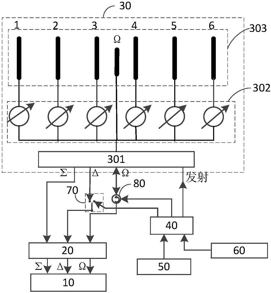
[0091] Please refer to figure 1 , which is a structural block diagram of an array antenna system provided in Embodiment 1 of the present application, including:

[0092] host 10;

[0093] The three-channel receiver 20 is connected with the host 10;

[0094] The radio frequency front end 30 is connected with the three-channel receiver 20 through the transceiver channel;

[0095] A channel switch 40, the first end of the channel switch 40 is connected to the radio frequency front end 30;

[0096] The calibration source 50 is connected to the second end of the channel switching switch 40;

[0097] The transmitter 60 is connected to the third end of the channel switch 40;

[0098] Wherein, when the host 10 controls the channel switching switch 40 to be in the connection state connected to the calibration source 50, the host 10 determines the first calibration mode of the array antenna system, and controls at least one channel corresponding to the first calibration mode In the w...

Embodiment 2

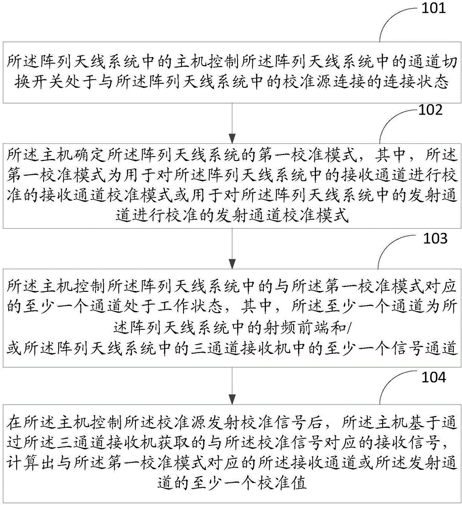
[0110] Based on the same inventive concept as Embodiment 1 of this application, please refer to figure 2 , is an antenna calibration method provided in Embodiment 2 of the present application, which is applied to an array antenna, and the method includes:

[0111] S101: The host in the array antenna system controls the channel switching switch in the array antenna system to be in a connection state connected to the calibration source in the array antenna system;

[0112] S102: The host determines a first calibration mode of the array antenna system, wherein the first calibration mode is a receiving channel calibration mode used to calibrate receiving channels in the array antenna system or is used to calibrate all A transmission channel calibration mode for calibrating the transmission channels in the array antenna system;

[0113] S103: The host controls at least one channel corresponding to the first calibration mode in the array antenna system to be in the working state, ...


PUM


Abstract

The invention discloses an array antenna system and a calibration method of an antenna. The array antenna system comprises a host computer, a three-channel receiving machine, a radio frequency front end, a channel switching switch, a calibration source and a transmitter, wherein the three-channel receiving machine is connected with the host computer; the radio frequency front end is connected with the three-channel receiving machine through a transceiver channel; the first end of the channel switching switch is connected with the radio frequency front end; the calibration source is connected with the second end of the channel switching switch; and the transmitter is connected with the third end of the channel switching switch. When the host computer controls the channel switching switch to be connected with the calibration source in a connecting condition, a first calibration mode of the array antenna system is determined through the host computer, and at least one channel corresponding to the first calibration mode is controlled in a working condition; and after the host computer controls the calibration source to transmit a calibration signal, the host computer calculates at least one calibration value of the transceiver channel based on a receiving signal acquired by the three-channel receiving machine.

Description

technical field [0001] The invention relates to the field of electronic technology, in particular to an array antenna system and an antenna calibration method. Background technique [0002] The phased array system is an antenna that realizes beam scanning in a designated space through electronic control. Its capabilities of rapid beam scanning, beam shape agility, and spatial power combining make it more and more widely used. However, important indicators such as sidelobe level, beam pointing, beam width and gain of the phased array antenna will be affected by factors such as frequency, channel error, installation tolerance, etc. These factors are finally reflected in the feed amplitude of each unit channel of the antenna and phase inconsistencies. At the same time, after the receiving beam is formed, the sum, difference, and control three-channel amplitude (or dual-channel) and single-pulse processing methods are generally used for sidelobe processing and azimuth measureme...

Claims


Application Information

Patent Timeline
IPC IPC(8): H01Q21/00H04B17/12
CPCH01Q21/00H04B17/12
Inventor 夏鸿张抒漆杨
Owner SICHUAN JIUZHOU ELECTRIC GROUP
Why Eureka
Try Eureka