WiFi-frequency-band-based rectification antenna with harmonic wave suppression

A rectifier antenna and harmonic suppression technology, applied in the direction of antenna, antenna coupling, antenna components, etc., can solve the problems of decreased rectification efficiency, large insertion loss, etc., to reduce insertion loss, reduce the amplitude of impedance change, reduce The effect of the via link

Inactive Publication Date: 2017-02-22
SYSU CMU SHUNDE INT JOINT RES INST +1
View PDF2 Cites 20 Cited by
  • Summary
  • Abstract
  • Description
  • Claims
  • Application Information

AI Technical Summary

Problems solved by technology

However, the introduction of the input filter is often accompanied by...

Method used


Image

  • WiFi-frequency-band-based rectification antenna with harmonic wave suppression
  • WiFi-frequency-band-based rectification antenna with harmonic wave suppression
  • WiFi-frequency-band-based rectification antenna with harmonic wave suppression

Examples


Embodiment 1

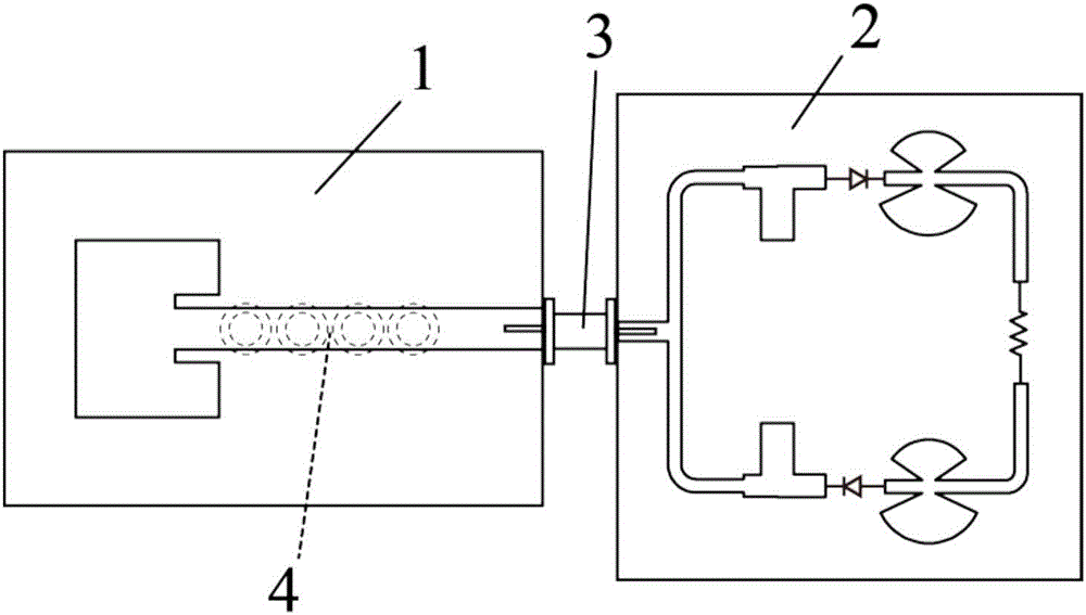
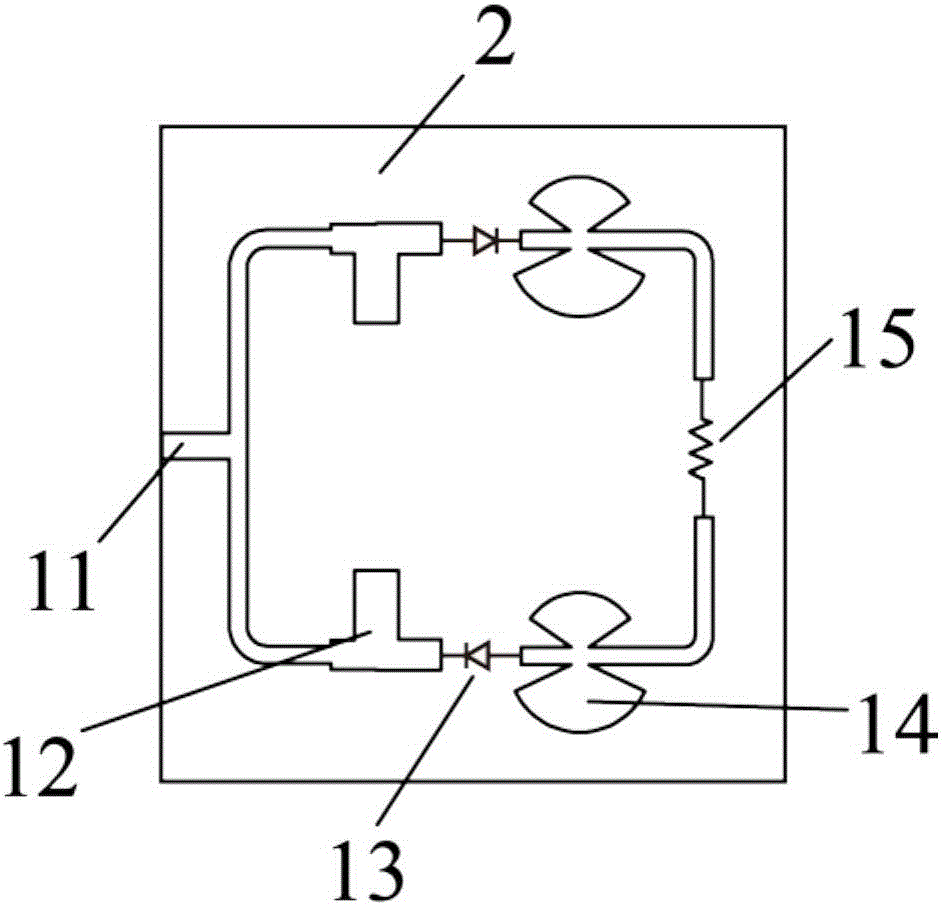
[0029] Such as figure 1 As shown, the rectenna includes a microstrip receiving antenna 1 and a microstrip differential rectifying circuit 2 , both of which are connected through a joint 3 . When microwaves in the WiFi frequency band are transmitted to the microstrip receiving antenna 1, the microstrip receiving antenna 1 receives the microwave energy. At the same time, the annular groove 4 on the ground plane filters out the high-order harmonic components in the microwave energy, and transmits the microwave energy through the connector 3. It is transmitted to the microstrip differential rectification circuit 2.

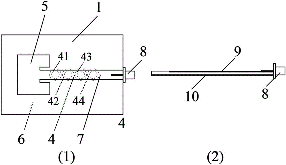
[0030] Such as figure 2 As shown, the microstrip receiving antenna 1 includes a T-shaped radiation surface 5 , an annular groove 4 , a ground 6 , a feeding microstrip line 7 and an SMA head 8 . Among them, the T-shaped radiating surface 5 and the feeding microstrip line 7 constitute the radiation unit 9 of the antenna, the ground 6 and the annular groove 4 constitu...


PUM


Abstract

The invention discloses a WiFi-frequency-band-based rectification antenna with harmonic wave suppression. The rectification antenna comprises a WiFi-frequency-band-based harmonic wave suppressing microstrip receiving antenna and a microstrip differential rectification circuit. The output end of the microstrip receiving antenna is connected with the input end of the microstrip differential rectification circuit. The microstrip differential rectification circuit includes a 50-ohm impedance wire, a branch T type impedance matching unit, a branch rectification unit, and a branch output filter and a load. The 50-ohm impedance wire is used as the input end at the input port of the microstrip differential rectification circuit and is connected with the output end of the receiving antenna. The output end of the input port leads out two branches. The input ends of the two branches are connected through a T type knot and the output ends pass successively the branch impedance matching unit, the branch rectification unit, and the branch output filter, and is finally connected with the load. The diodes of the branch rectification unit are connected in reverse direction.

Description

technical field [0001] The invention relates to the field of wireless energy transmission, and relates to a rectifying antenna at a receiving end of a microwave energy transmission system, in particular to a rectifying antenna with harmonic suppression based on a WiFi frequency band. Background technique [0002] Microwave Power Transmission (MPT, Microwave Power Transmission) is a new technology that uses microwaves as a carrier to transmit energy in vacuum or free space. Compared with the traditional wired energy transmission technology, MPT technology has incomparable advantages in many application scenarios, so that in recent years, MPT technology has received more and more attention and has been gradually applied to energy harvesting, radio frequency Identification, wireless charging, and sensor networks to name a few. [0003] The rectenna (Rectenna) at the receiving end of the microwave energy transmission system is mainly composed of two parts: the receiving antenna...

Claims


Application Information

Patent Timeline
IPC IPC(8): H01Q23/00H01Q1/36H01Q1/50H01Q1/52
CPCH01Q1/36H01Q1/50H01Q1/521H01Q23/00
Inventor 谭洪舟付超区俊辉谢昭家
Owner SYSU CMU SHUNDE INT JOINT RES INST
Why Eureka
Try Eureka