
A low voltage switch cabinet

A low-voltage switchgear and cabinet body technology, applied in the field of low-voltage switchgear, can solve problems such as potential safety hazards and switchgear maintenance, and achieve the effects of preventing electric shock accidents, reducing hazards and losses, and improving safety performance

Active Publication Date: 2018-08-03
DAISHAN POWER SUPPLY CO STATE GRID ZHEJIANG ELECTRIC POWER CO +2
View PDF8 Cites 0 Cited by
  • Summary
  • Abstract
  • Description
  • Claims
  • Application Information

AI Technical Summary

Problems solved by technology

[0003] The technical problem to be solved by the present invention is to provide a low-voltage switchgear to solve the problem of potential safety hazards in the maintenance of existing switchgears

Method used


Image

  • A low voltage switch cabinet
  • A low voltage switch cabinet
  • A low voltage switch cabinet

Examples


Embodiment 1

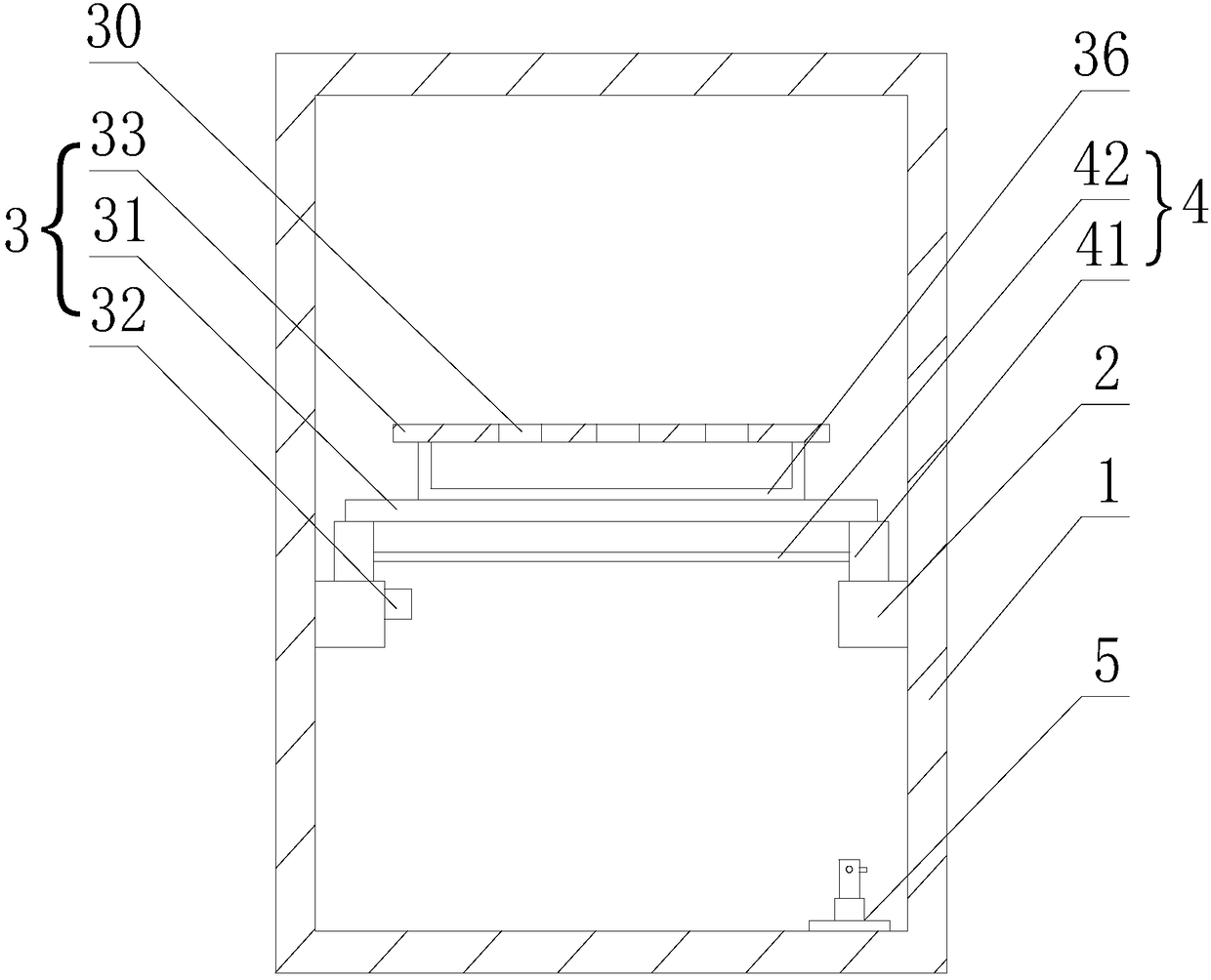
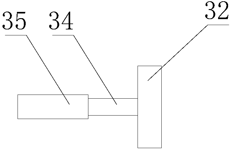
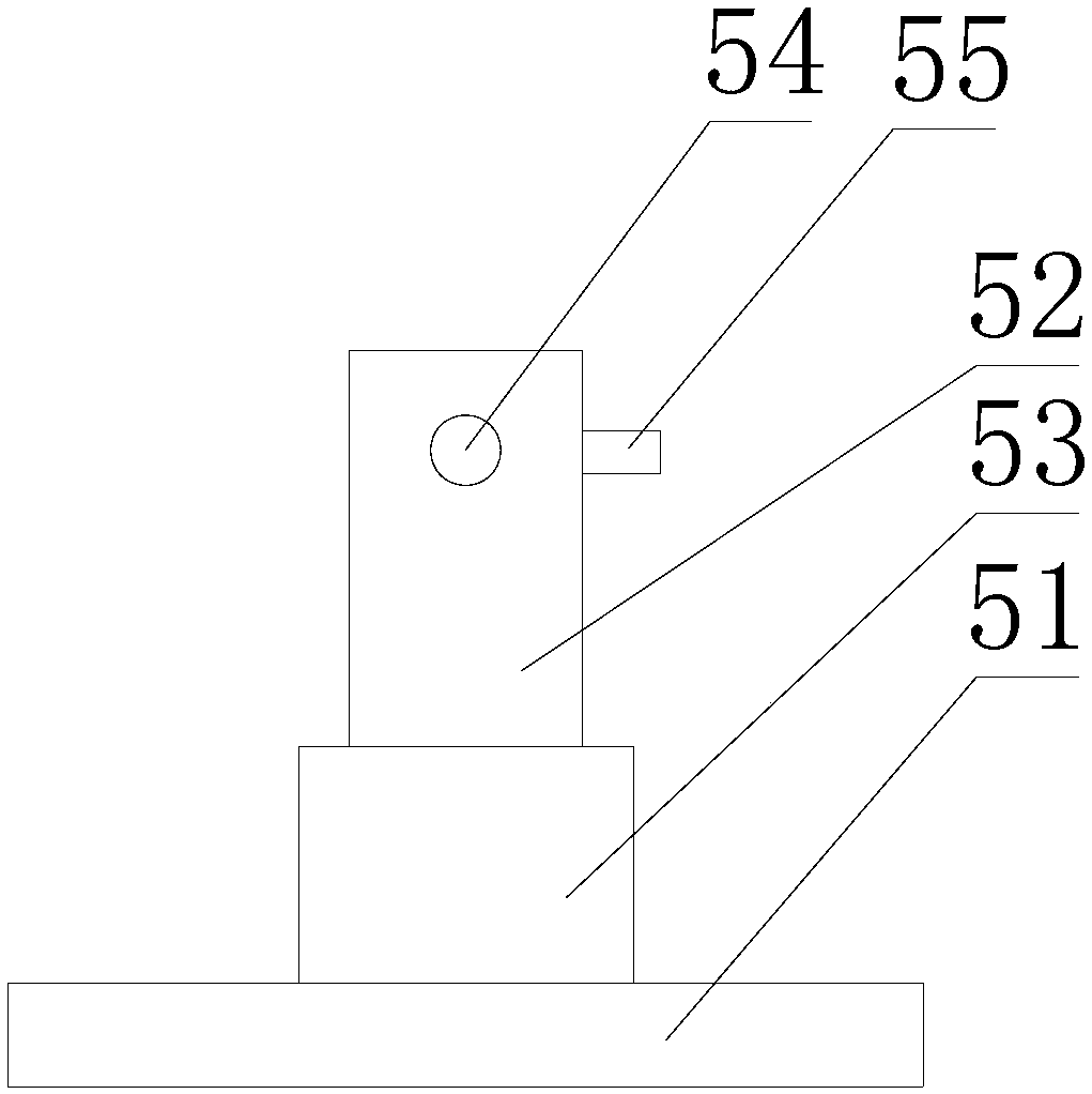
[0022] Such as figure 1 , figure 2 , image 3 As shown, a low-voltage switch cabinet includes a cabinet body 1 and a handcart rail 2 arranged in the cabinet body 1. A grounding protection device 3 is installed on the handcart rail 2. The grounding protection device 3 includes a baffle 31, a handle 32 and Mounting plate 33, the mounting plate 33 is arranged on the baffle plate 31, the baffle plate 31 is provided with a sliding assembly 4, the sliding assembly 4 controls the baffle plate 31 to move in the axial direction of the handcart track 2, and the handle 32 is installed on the sliding assembly 4 Control the sliding and locking of the sliding assembly, the handle 32 is installed in the connecting hole 30 to realize the fixing of the grounding wire, and the positioning assembly 5 for hanging the grounding wire is arranged in the cabinet 1 .

[0023] The sliding assembly 4 includes a guide slider 41 and a connecting shaft 42. A guide slider 41 is provided at both ends of t...

Embodiment 2

[0026] A low-voltage switchgear as described in Embodiment 1, this embodiment has the following differences: the connecting hole 30 is a through hole, the bolt part 34 is provided with a nut, and the nut is arranged on the upper end and / or lower end of the mounting plate 33, The bolt part is fixedly connected to the mounting plate through the nut, the connection is reliable, the installation and disassembly are convenient, the use effect is good, and the stability of the bolt part can be guaranteed.

[0027] When in use, the handcart is pulled out of the cabinet 1, and the handle 32 is used to control the rotation of the handle 35 to realize the movement of the sliding assembly 4 in the axial direction of the handcart track 2. When the baffle 31 contacts the front wheel of the handcart At this time, the handle 32 controls the handle 35 to lock the sliding assembly 4, thereby preventing accidents caused by the misoperation of the front wheel, and then the handle 32 is disassembl...


PUM


Abstract

The invention relates to a low-voltage switch cabinet, and the switch cabinet comprises a cabinet body and a handcart track. The handcart track is provided with a grounding protection device, and the grounding protection device comprises a baffle plate, a handle, and an installation plate. The installation plate is disposed on the baffle plate, and the baffle plate is provided with a sliding assembly. The sliding assembly controls the baffle plate to move in the axial direction of the handcart track. The handle is disposed on the sliding assembly to control the sliding and locking of the sliding assembly. The handle is disposed at a connection hole to achieve the fixing of a grounding line. The interior of the switch cabinet is provided with a positioning assembly which is used for hooking the grounding line. The switch cabinet is advantageous in that the temporary grounding setting of the switch cabinet is achieved through the grounding protection device during maintenance; the switch cabinet can effectively prevent an electric shock accident; a zero line in a grounding device can reduce the voltage during the electric leakage of equipment; the switch cabinet improve the work efficiency of an operator, reduces the labor intensity, reduces the danger and loss caused by wrong operation, improves the application safety factor of the equipment, and guarantees that a maintainer is timely prevented from continuing to carry out maintenance during misoperation.

Description

technical field [0001] The invention relates to a low-voltage switch cabinet. Background technique [0002] With the rapid development of social economy, people's demand for electricity is increasing, and electricity plays a vital role in people's life and production process. The high and low voltage switchgear is mainly responsible for converting high voltage into low voltage, and finally As a key role in the power field, the equipment should be inspected and repaired regularly during use to ensure that substations and power supply bureaus can normally distribute electricity to residents, and to ensure the normal production and life of people. Social stability, however, there are many problems in the development of my country's electric power industry, which are likely to bring some safety hazards, cumbersome operation, high cost, low efficiency of operators, and danger during maintenance. Contents of the invention [0003] The technical problem to be solved by the present...

Claims


Application Information

Patent Timeline
Patent Type & Authority Patents(China)
IPC IPC(8): H02B11/167
CPCH02B11/167
Inventor 虞伟贺伟军陈胜王珂艳戴浩斌
Owner DAISHAN POWER SUPPLY CO STATE GRID ZHEJIANG ELECTRIC POWER CO
Learn More