Mould casting type flexible direct-current cable soft joint reaction force cone structure designing method

A technology of reaction force cone and DC cable, which is applied in the direction of cable accessories, cable installation, electrical components, etc., can solve the problems of lack of theoretical support, etc., and achieve the effect of ensuring long-term safety and reliability, avoiding the accumulation of field strength, and uniform electric field

Inactive Publication Date: 2017-02-22
NANJING NARI GROUP CORP +3
View PDF3 Cites 10 Cited by
  • Summary
  • Abstract
  • Description
  • Claims
  • Application Information

AI Technical Summary

Problems solved by technology

At present, the structural design of injection-molded flexible DC cable joints mostly refers to the design principles of prefabricated joints or on-site construction experience, lacking the necessary theoretical support. The patent of this invention proposes relevant structural design theories in terms of structural design of injection-molded cable joints

Method used


Image

  • Mould casting type flexible direct-current cable soft joint reaction force cone structure designing method
  • Mould casting type flexible direct-current cable soft joint reaction force cone structure designing method
  • Mould casting type flexible direct-current cable soft joint reaction force cone structure designing method

Examples


Embodiment 1

[0137] This embodiment is an injection molded flexible straight submarine cable flexible joint with a rated voltage of ±525kV.

[0138] For ±525kV injection molded flexible straight submarine cable flexible joint, U=525kV; ρ 0 =10 16 Ω·m;

[0139] α=0.15 1 / °C; γ=2.2; r c =34.45mm; R=64.45mm; ρ T1 = 3.5 TΩ m;

[0140] W c = 30.5W;

[0141] Substituting the above values ​​into formula (14), the expression can be obtained:

[0142]

[0143] Substitute y=64.45 into the above formula to get the length L of the reaction force cone curve C :

[0144]

[0145] L C =392.5mm

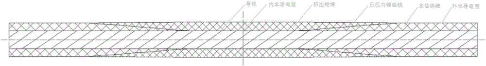
[0146] The flexible joint structure of ±525kV injection molded flexible straight cable is as follows: image 3 shown.

Embodiment 2

[0148] This embodiment is an injection molded flexible straight submarine cable flexible joint with a rated voltage of ±200kV.

[0149] For ±200kV injection molded flexible straight submarine cable flexible joint, U=200kV; ρ 0 =10 16 Ω·m;

[0150] α=0.15 1 / °C; γ=2.2; r c = 20.4mm; R = 35.4mm; R n =36.4mm; ρ T1 = 3.5 TΩ m;

[0151] W c =58W;

[0152] Substituting the above values ​​into formula (14), the expression can be obtained:

[0153]

[0154] Substitute y=35.4 into the above formula to get the length L of the reaction force cone C :

[0155]

[0156] L C =156.4mm

[0157] The flexible joint structure of ±200kV injection molded flexible straight cable is as follows: Figure 4 shown.


PUM


Abstract

The invention discloses a mould casting type flexible direct-current cable soft joint reaction force cone structure designing method. The method is characterized by comprising the following steps: (I) determining the parameters of a cable conductor, and calculating the temperature difference between the insulating inner and outer surfaces of a direct-current cable body; (II) calculating the electric field intensity at the center of a direct-current cable insulation layer; (III) calculating a direct-current cable soft joint reaction force cone curve equation; and (IV) obtaining a reaction force cone structure to obtain the specific structure of the cable soft joint. The method has the following advantages: the problem of electrical resistivity mismatching between the cable body insulation material and the mould casting insulation material and consequent field intensity accumulation at the interface of the two are avoided; meanwhile, the influence of temperature and electric field factors on the electrical resistivity is considered, electric field distribution in flexible direct-current cable terminal insulation is proposed, and a theoretical basis is provided for designing a flexible direct-current cable soft joint; uniform electric field at the flexible direct-current cable soft joint is guaranteed; and the electrical property requirement of the whole flexible direct-current cable system on the joint is met, and long-term safety and reliability of the flexible direct-current cable system are guaranteed.

Description

technical field [0001] The invention relates to a design method for a reaction force cone structure of an injection molded flexible DC cable soft joint, belonging to the technical field of DC cable accessories. Background technique [0002] With the rise of clean energy such as solar energy and wind energy, coupled with the advantages of high transmission efficiency, small line loss, simplicity of power direction control, and superior economic performance, flexible DC transmission technology has received more and more attention. It has been applied in many projects. The DC cable connector is an essential cable connector in the flexible DC transmission system, and its performance is directly related to the normal operation of the entire flexible DC transmission system. [0003] According to the type of process, DC cable joints are divided into two types: injection molding type and prefabricated type. There are two types of prefabricated cable joints: the one with the larges...

Claims


Application Information

Patent Timeline
Patent Type & Authority Applications(China)
IPC IPC(8): H02G15/064
CPCH02G15/064
Inventor 陈龙啸杨黎明朱智恩
Owner NANJING NARI GROUP CORP
Why Eureka
Try Eureka