Hollow fiber membrane module and manufacturing method therefor

A manufacturing method and technology of fiber membranes, applied in the field of hollow fiber membrane modules and their manufacture, can solve problems such as low filling efficiency of hollow fiber membranes, difficulty in miniaturization of modules, and difficulty in improving filtration performance, so as to improve filling efficiency and filtration flow rate increased effect

Inactive Publication Date: 2017-02-22
MITSUBISHI CHEM CORP
View PDF4 Cites 0 Cited by
  • Summary
  • Abstract
  • Description
  • Claims
  • Application Information

AI Technical Summary

Problems solved by technology

However, if the hollow fiber membranes are simply bent into a U-shape, especially when the hollow fiber membrane bundle is housed in a cylindrical case, the filling efficiency of the hollow fiber membranes becomes low, making it difficult to improve the filtration efficiency. performance
That is, when the hollow fiber membranes are simply bent into a U-shape to form a hollow fiber membrane bundle, the hollow fiber membrane bundle has a substantially rectangular shape or an oblong shape in plan view. Gaps are formed between the inner surfaces of the circular shell when viewed from above, and as a result, the filling efficiency becomes low
In addition, the filling efficiency becomes so low that it is difficult to miniaturize the components in order to obtain predetermined filtration performance

Method used


Image

  • Hollow fiber membrane module and manufacturing method therefor
  • Hollow fiber membrane module and manufacturing method therefor
  • Hollow fiber membrane module and manufacturing method therefor

Examples


Embodiment

[0100] Hereinafter, examples of the hollow fiber membrane module of the present invention and its manufacturing method will be described, but the present invention is not limited to the following examples.

[0101] (Manufacturing of hollow fiber membrane modules)

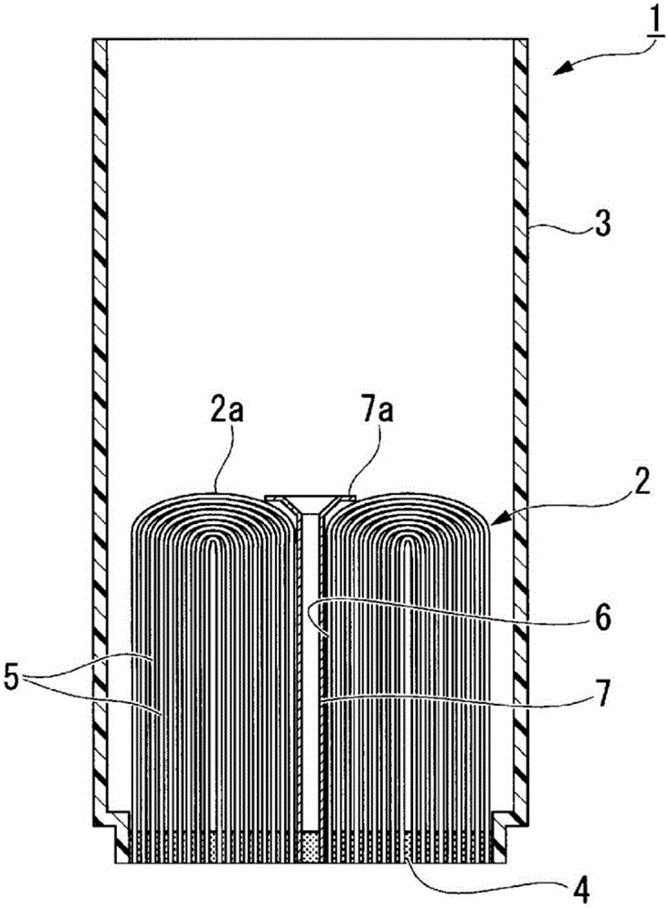
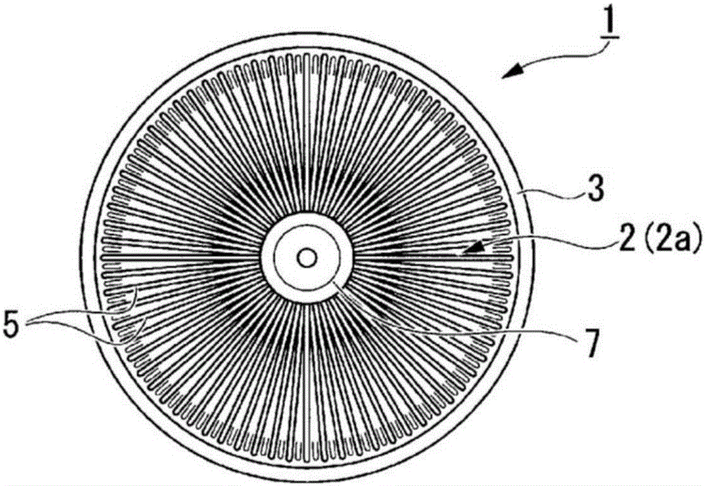
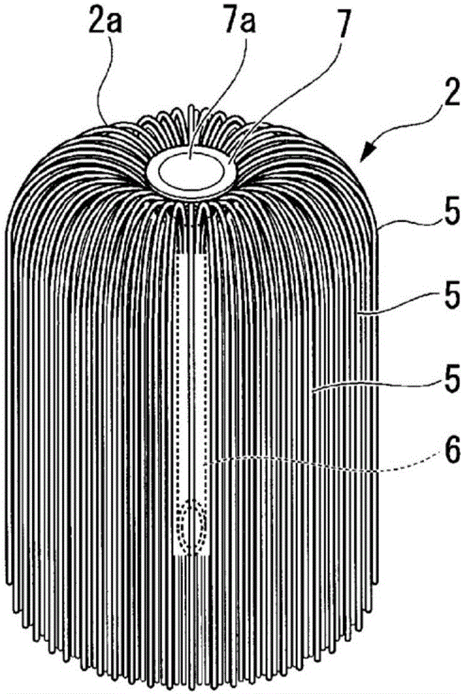
[0102] In this embodiment, first, after forming Figure 1A and Figure 1B After the hollow fiber membrane bundle 2 as shown in the Figure 7 A hollow fiber membrane module 1A was produced with a casing 30 as shown in .

[0103] That is, in this embodiment, first, one end side of a plurality of hollow fiber membranes 5 formed of polysulfone having a fiber length (membrane web) of 65 mm (effective fiber length: 51 mm; perfusion length: 8 mm, cutting length: 6 mm) and The mandrels are inserted together into the cylinder and held in place.

[0104] Next, the hollow fiber membrane 5 is bent in a U-shape from the central portion of the cylindrical body toward the inner wall portion so that the void portion 6 is formed...


PUM

PropertyMeasurementUnit
pore sizeaaaaaaaaaa
thicknessaaaaaaaaaa
lengthaaaaaaaaaa

Abstract

This hollow fiber membrane module (1) is configured so that a hollow fiber membrane bundle (2), formed by bending multiple hollow fiber membranes (5) into a U-shape, is filled into a cylindrical case (3) and a fixing resin (4) is injected into the case (3) to fix the side of the hollow fiber membrane bundle (2) opposite a bent section (2a) thereof to the bottom of the case (3). The hollow fiber membranes (5) are bent into a U-shape inside of the case (3) and at a substantially central part of the hollow fiber membrane bundle (2), a void portion (6) is formed along the height direction of the case (3). A core rod is inserted into the void portion (6).

Description

technical field [0001] The present invention relates to a hollow fiber membrane module and a manufacturing method thereof. [0002] This application claims priority based on Japanese Patent Application No. 2014-046873 for which it applied in Japan on March 10, 2014, and uses the content of this Japanese Patent Application here. Background technique [0003] In recent years, water purifiers for purifying tap water have been widely used in households and the like. As such a water purifier, many water purifiers using a hollow fiber membrane module as a filter material are known. [0004] As the above-mentioned hollow fiber membrane module, there is known a hollow fiber membrane module formed by packing a hollow fiber membrane bundle formed by bending a large number of hollow fiber membranes into a cylindrical casing, and injecting a fixing material into the casing. A resin is used to fix the hollow fiber membrane bundle to the bottom of the housing on the side opposite to the...

Claims


Application Information

Patent Timeline
Patent Type & Authority Applications(China)
IPC IPC(8): B01D63/02B01D63/00B01D63/04C02F1/44
CPCB01D63/04C02F1/003C02F1/283C02F1/444C02F2201/006B01D63/024B01D63/0241B01D63/021B01D69/08B01D65/003B01D2313/205B01D2313/042
Inventor 板仓正则伊藤正则竹田初美
Owner MITSUBISHI CHEM CORP
Why Eureka
Try Eureka