Eureka AIR delivers breakthrough ideas for toughest innovation challenges, trusted by R&D personnel around the world.

Pneumatic vehicle tyre

A technology of pneumatic tires and tires, applied in tire measurement, vehicle parts, tire parts and other directions, can solve problems such as adverse effects on wet performance of vehicle pneumatic tires, and achieve the effect of smooth direction

Active Publication Date: 2017-02-22
CONTINENTAL REIFEN DEUTSCHLAND GMBH
View PDF6 Cites 2 Cited by
  • Summary
  • Abstract
  • Description
  • Claims
  • Application Information

AI Technical Summary

Problems solved by technology

Here, these known post-cut indicators constitute, by their positioning in the groove base, stagnation points for the drainage of water, which can be detrimental to the pneumatic tire of a vehicle when the tread depth gradually decreases due to wear. Wetland performance adversely affected

Method used


Image

  • Pneumatic vehicle tyre
  • Pneumatic vehicle tyre
  • Pneumatic vehicle tyre

Examples


Embodiment Construction

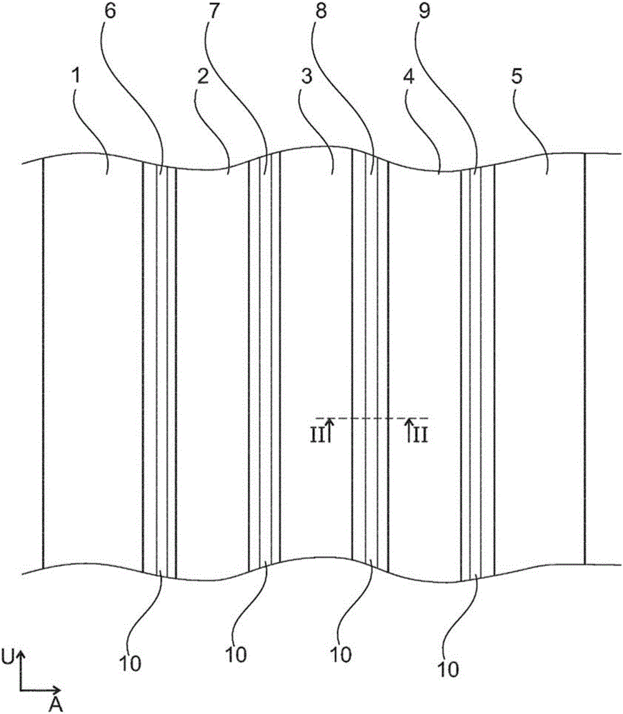
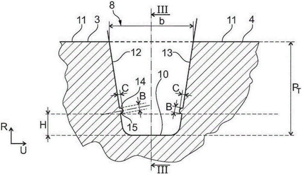
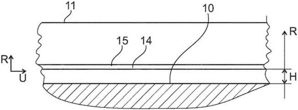
[0032] Figure 1 to Figure 3 Shown is a tread pattern of a pneumatic tire for commercial vehicles, which has tread patterns arranged side by side with each other in the axial direction A of the pneumatic tire for the vehicle, extending over the entire circumference of the pneumatic tire for the vehicle and extending in the circumferential direction U A plurality of circumferential ribs 1, 2, 3, 4 and 5 in upward orientation. exist figure 1 In the embodiment shown, the circumferential rib 1 forms a left shoulder rib and the circumferential rib 5 forms a right shoulder rib. The circumferential rib 1 and the circumferential rib 2 are arranged alongside each other in the axial direction A and are axially spaced apart from each other by a circumferential groove 6 extending over the entire circumference of the vehicle pneumatic tire and oriented in the circumferential direction U . The circumferential rib 2 and the circumferential rib 3 are arranged next to each other in the axi...


PUM


Abstract

Tread profile of a pneumatic vehicle tyre - in particular for commercial vehicles - comprising a regroovable tread profile with radially raised profile elements (1, 2, 3, 4, 5) and with grooves (6, 7, 8, 9), which respectively separate two adjacent profile elements (1, 2, 3, 4, 5) from one another, wherein the grooves (6, 7, 8, 9) are bounded inwards in the radial direction R by a groove base (10) and on both sides in the axial direction by a profile element flank, forming the groove wall (12, 13), and wherein at least one regrooving indicator (14) for indicating the regrooving depth is respectively formed in one or more grooves (3), characterized in that, in at least one groove (8), all of the regrooving indicators (14) formed therein are formed in a groove wall (12) at a height H measured in the radial direction R of H>0mm above the groove base (10), wherein the height H corresponds to the maximum radial abrasion position of the tyre for regrooving.

Description

technical field [0001] The invention relates to a tread pattern of a pneumatic vehicle tire, in particular for commercial vehicles, having a recuttable tread pattern having a plurality of radially raised tread elements and having two phase Sipes in which adjacent lug units are separated from each other, wherein the lugs are bounded towards the inside in the radial direction R by a lug base and towards the sides in the axial direction by a lug unit constituting the lug walls The sides are limited, and wherein at least one subsequent cut indicator is respectively formed in the one or more grooves to indicate the subsequent cut depth. Background technique [0002] It is known to form vehicle pneumatic tires with a tread pattern in which a plurality of radially raised tread units are spaced apart from each other by sipe. Here, these tread patterns are formed with a tread depth optimized for the respective application. In this case, the sipe are formed maximally with a maximum ...

Claims


Application Information

Patent Timeline
IPC IPC(8): B60C11/24B60C11/13
CPCB60C11/042B60C11/24B60C2011/1338B60C11/0083B60C11/1307
Inventor 安德烈·卢茨弗洛里安·克里斯滕
Owner CONTINENTAL REIFEN DEUTSCHLAND GMBH
Why Eureka
Eureka Blog
Learn More