
Injection system and method for operating an injection system

An injection system and injector technology, applied in the direction of charging system, fuel injection control, engine components, etc., can solve the problems of pressure pulsation, adverse effects on injector metering accuracy, noise generation, etc., and achieve precise injection amount metering Effect

Inactive Publication Date: 2017-02-22
ROBERT BOSCH GMBH
View PDF4 Cites 0 Cited by
  • Summary
  • Abstract
  • Description
  • Claims
  • Application Information

AI Technical Summary

Problems solved by technology

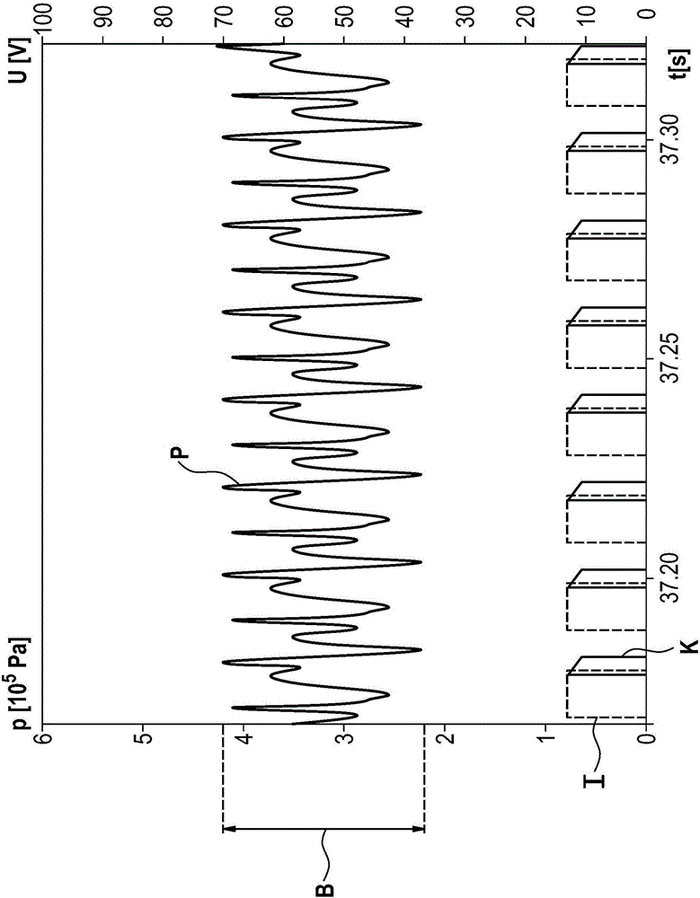
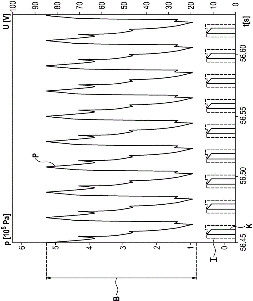
Here, it has now been established that pressure pulsations can occur at the injector inlet during operation, which adversely affects the dosing accuracy of the injector
In addition, during operation, unwanted noise generation can partially occur on the piston pump

Method used


Image

  • Injection system and method for operating an injection system
  • Injection system and method for operating an injection system
  • Injection system and method for operating an injection system

Examples


Embodiment Construction

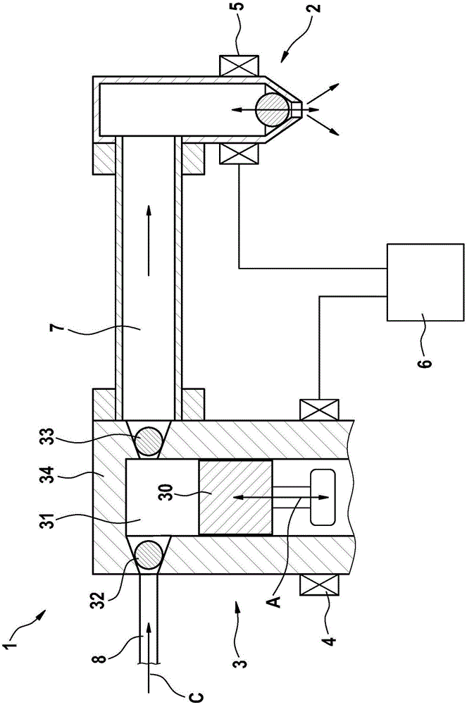
[0023] Refer to the appendix below Figures 1 to 3 The injection system 1 according to the preferred embodiment of the present invention is described in detail.

[0024] The injection system 1 includes an injector 2 and a piston pump 3 . The piston pump 3 is connected to the injector 2 via a pressure line 7 .

[0025] Piston pump 3 in figure 1 It is only schematically shown in , and includes a reciprocating piston 30 (double arrow A) in a cylinder 34 , a delivery chamber 31 , an inlet valve 32 and an outlet valve 33 . The pressure line 7 is here arranged downstream of the outlet valve 33 in the fuel flow direction.

[0026] Reference numeral 8 designates a fuel supply line, via which fuel can be drawn into the delivery chamber 31 in a known manner via an open inlet valve 32 (arrow C).

[0027] The piston pump 3 is operated by means of a first actuator 4 . The second actuator 5 is provided for operating the injector 2 .

[0028] like figure 1 As can be seen, the first ac...


PUM


Abstract

The invention relates to an injection system, comprising an injector (2), a piston pump (3) for conveying fuel to the injector (2), wherein the piston pump (3) comprises a first actuator (4) for actuating a piston (30), and a control unit (6), which is designed to control the piston pump (3) in dependence on control of the injector (2).

Description

technical field [0001] The present invention relates to an injection system for vehicles, in particular motorcycles, and to a method for operating such an injection system. Background technique [0002] Injection systems in two-wheeled vehicles generally have to be made to be very durable and compact. The injector is usually operated by the engine controller, and the injector injects fuel according to the operating state of the engine. Piston pumps usually run at a constant frequency to provide the required injection pressure on the injector. Here, it has now been established that during operation, pressure pulsations can occur at the injector inlet, which adversely affect the dosing accuracy of the injector. In addition, during operation, unwanted noise production occurs in part on the piston pump. SUMMARY OF THE INVENTION [0003] In contrast, an injection system according to the invention with the features of claim 1 has the advantage that unwanted noise production a...

Claims


Application Information

Patent Timeline
Patent Type & Authority Applications(China)
IPC IPC(8): F02M37/08F02D41/30F02D41/34
CPCF02D41/3845F02D41/3082F02D2250/04F02M37/08
Inventor S·芙洛F·尼切W·施特罗尔T·阿尔盖尔J·科雷克W·莫伊雷尔
Owner ROBERT BOSCH GMBH
Learn More