Valve device for controlling media flows of any type

A technology of any type and valve device, which is applied in the direction of valve device, valve operation/release device, valve lift, etc., can solve the problems of reduced cross-section and inability to easily realize the conversion process, etc., to achieve fast conversion process and improve function safety effect

Active Publication Date: 2017-02-22
RSG ELECTRONICS
View PDF9 Cites 5 Cited by
  • Summary
  • Abstract
  • Description
  • Claims
  • Application Information

AI Technical Summary

Problems solved by technology

Despite the advantages of noise reduction in the operation of the valve arrangement, there are also expectations for trouble-free and disturbance-free operation, especially with regard to functional safety
With this known solution, it is also not easy to achieve a very fast changeover process between establishing and re-disconnecting the connection of the guide medium between the various interface positions, which is caused by the throttle plate glued into the control tube. The cross section of the

Method used


Image

  • Valve device for controlling media flows of any type
  • Valve device for controlling media flows of any type
  • Valve device for controlling media flows of any type

Examples


Embodiment Construction

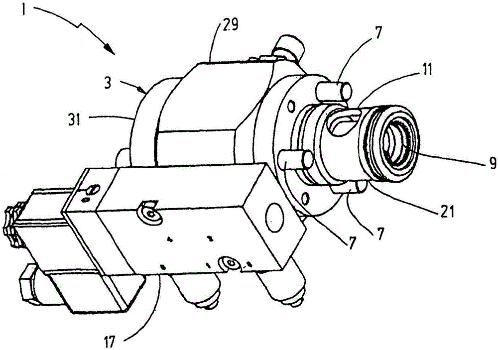
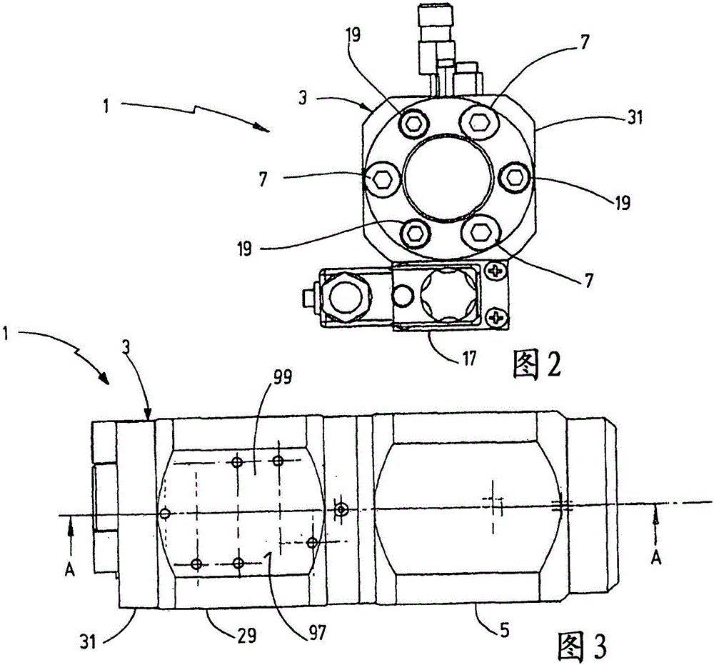
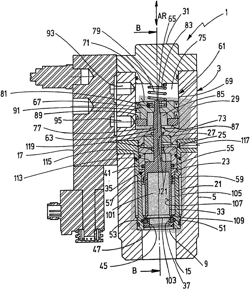
[0017] exist Figure 1 to Figure 5 shows a valve device 1 according to the invention for controlling a flow of any type of medium. The valve device 1 is constructed in the form of a cartridge case or cartridge and has a valve housing 3 , in particular of multi-part design, which can be fastened to the valve body 5 by means of three fastening elements 7 , for example in the form of screws. The valve housing 3 has an axial medium connection point 9 and, as a common radial medium connection point 11 , two radial bores extending transversely to the axial medium connection point. Within the scope of the invention, each medium connection point 9 or 11 can be a pressure supply input P, ​​and the corresponding other medium connection point 11 or 9 can be a consumer output A. In the shown case, the connection point 11 is the pressure supply input P, ​​and the connection point 9 corresponds to the consumer connection A. As shown in FIG. In the engaged position of the valve housing 3 i...


PUM


Abstract

The invention relates to a valve device (1) for controlling media flows of any type by means of at least one valve control piston (33), which is guided in a longitudinally movable manner in a valve housing (3) and which controls a media connection between at least two media connection points (9, 11) in the valve housing (3), of which at least one media connection point is a pressure supply inlet (P) and at least one other media connection point is a load outlet (A), wherein the valve control piston (33) is guided in the valve housing (3) with pressure equalization by means of at least one equalizing apparatus (35) at least with respect to the media pressure at the respective pressure supply inlet (P).

Description

technical field [0001] The invention relates to a valve arrangement for controlling a flow of any type of medium by means of at least one valve control piston which is guided longitudinally displaceably in a valve housing and controls at least two medium connections in the valve housing Media connections between locations, at least one of which is a pressure supply input and at least one other media connection location is a consumer outlet. Background technique [0002] A valve arrangement in the form of a coaxial valve is known from DE 199 01 253 B4, which has a housing body which is arranged between two media connection points in the form of an inlet connection and a discharge connection, In this case, the housing body is an extruded part, and a seal is arranged between the inlet connection and the extruded part and between the outlet connection and the extruded part, respectively. In a further development of this solution, a control tube for such a coaxial valve is known...

Claims


Application Information

Patent Timeline
Patent Type & Authority Applications(China)
IPC IPC(8): F16K31/122
CPCF16K31/1221F16K1/34F16K1/46F16K27/02F16K3/267
Inventor R·埃伯哈德
Owner RSG ELECTRONICS
Why Eureka
Try Eureka