
Industrial camera cylinder detection method

A detection method and technology of industrial cameras, which are applied in measurement devices, material analysis by optical means, instruments, etc., can solve problems such as large space, high cost, and complex structure.

Active Publication Date: 2017-03-01
北京凯视佳光电设备有限公司
View PDF10 Cites 21 Cited by
  • Summary
  • Abstract
  • Description
  • Claims
  • Application Information

AI Technical Summary

Problems solved by technology

[0010] 1. Two cameras are required, one line array camera collects images of the side surface of the cylinder, analyzes defects, and the other area array camera collects the outer contour of the cylinder, and calculates the diameter and height of the cylinder; two installation stations need to be designed for the two cameras, and space is required Large, complex structure, difficult synchronization control, high cost
[0011] 2. The speed of the line array camera is fast. Generally, it is a camera link interface or a Gigabit network interface. It needs to be equipped with a dedicated acquisition card to work, and the overall solution cost is high.

Method used


Image

  • Industrial camera cylinder detection method
  • Industrial camera cylinder detection method
  • Industrial camera cylinder detection method

Examples


Embodiment Construction

[0024] The working principle of the present invention is as follows:

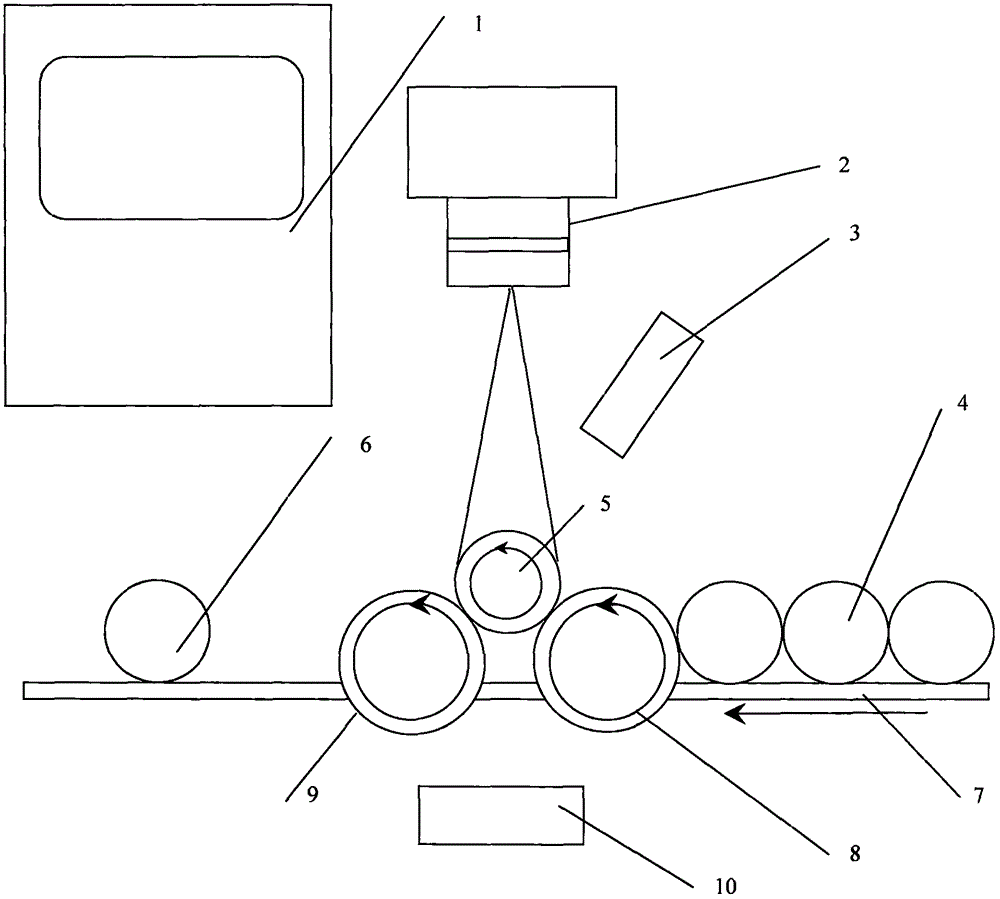
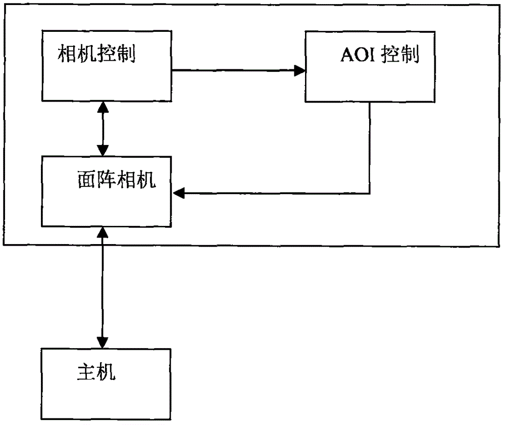
[0025] as attached figure 1 , attached figure 2 And attached image 3 As shown: the workpiece 4 to be inspected is transmitted to the feeding driving wheel 8 by the driving synchronous belt 7, and the workpiece is transmitted to the inspection station 5 by the feeding driving wheel 8. Rotate under the drive of 9, turn on the backlight 10 at this time, set the camera 2 to work as the area array sampling mode, collect the surface array image of the outer contour of the workpiece 5 under inspection, and calculate the diameter and height of the workpiece 5 under inspection; subsequently, by and The encoder with the drive wheel 8 coaxially obtains the rotation speed of the workpiece, calculates the line scan frequency, changes the camera to work in line array mode, sets the line scan frequency, turns on the line scan light source 3, collects the side surface image of the workpiece 5, and identifies the surfac...


PUM


Abstract

The invention relates to an industrial camera cylinder detection method. A workpiece to be detected is sent to a feed driving wheel by a driving synchronous belt, and the workpiece is then sent to a detection station by the feed driving wheel. When the workpiece reaches the detection station, the workpiece is driven by a driving wheel to rotate. At the moment, backlight is turned on, operation mode of a camera is set to be an area-array sampling mode so as to acquire an outer contour area-array image of the detected workpiece, and diameter and height of the detected workpiece are calculated. Then, rotating speed of the workpiece is obtained by an encoder which is coaxial with the driving wheel; linear scan frequency is calculated; the operation mode of the camera is set to be a linear array mode; linear scan frequency is set; a linear-scan light source is turned on; a lateral surface image of the workpiece is acquired, surface defects of the workpiece are recognized, and the detection is finished. According to the detection result, whether the workpiece is qualified and the grade of the workpiece are judged, so as to classify the workpiece.

Description

[0001] (1) Technical field [0002] The invention relates to the field of industrial camera detection, in particular to the field of using the industrial camera to detect cylindrical workpieces. [0003] (2) Background technology [0004] With the rapid development of machine vision image sensors, industrial cameras are basically divided into line-scan cameras and area-scan cameras in terms of scanning principles, and the scanning speed is getting higher and higher. 500FPS (refresh rate). In current inspection applications, line scan cameras are mainly used for printing inspection and planar defect inspection; area array cameras are used for contour size inspection, image processing comparison, positioning and other requirements. [0005] In recent years, CMOS image sensor technology has developed rapidly. The exposure time of the area array sensor with global exposure can be controlled at about 10us, and the output control function is powerful. The 1-line output can be realiz...

Claims


Application Information

Patent Timeline
IPC IPC(8): G01N21/952
CPCG01N21/952
Inventor 郭坡柯有勇
Owner 北京凯视佳光电设备有限公司
Learn More