Object-holding device

A technology for holding devices and objects, applied in biochemical cleaning devices, enzymology/microbiology devices, tissue cell/virus culture devices, etc., can solve the problem of complex structure of the holding device, inability to obtain the dispersion effect of cell agglutination, Cell clots get rid of other problems

Active Publication Date: 2017-03-01
YAMAHA MOTOR CO LTD
View PDF7 Cites 2 Cited by
  • Summary
  • Abstract
  • Description
  • Claims
  • Application Information

AI Technical Summary

Problems solved by technology

However, the structure of the holding device with the vibration mechanism will be complicated
In addition, when the holding part has a shape of a concave part, once the cell aggregates are embedded in the concave part, the cell aggregates cannot be released from the concave part even with a slight vibration, and the desired degree of dispersion effect of the cell aggregates may not be obtained.

Method used


Image

  • Object-holding device
  • Object-holding device
  • Object-holding device

Examples


no. 1 approach >

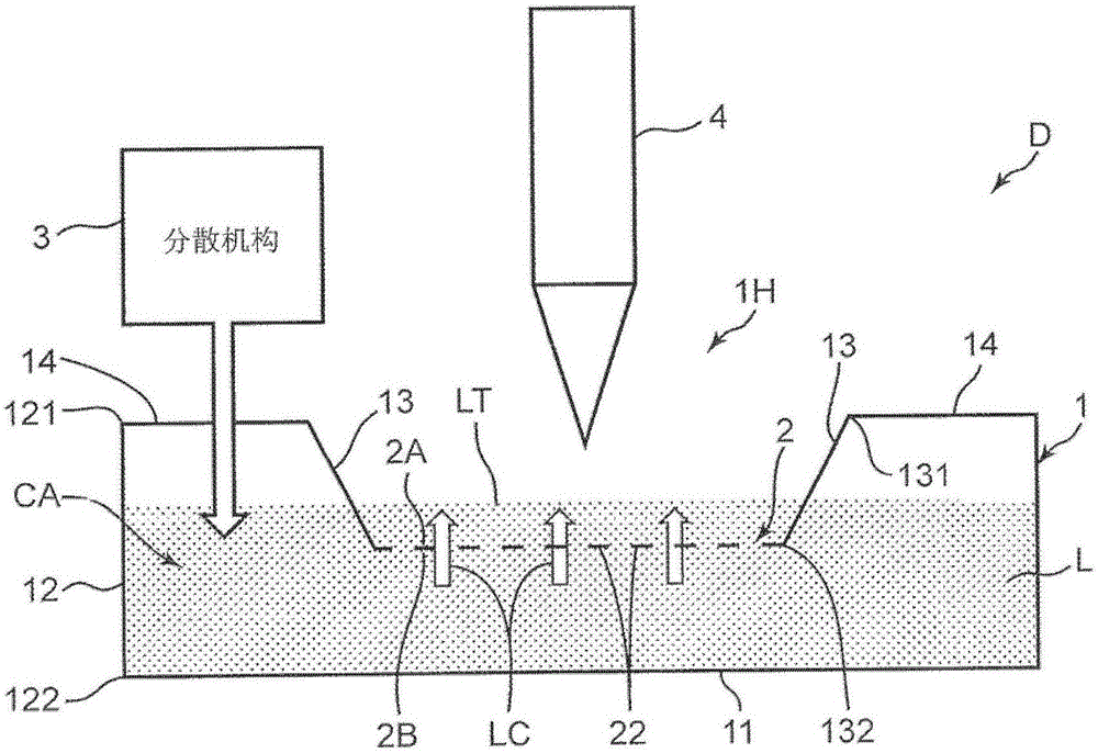
[0067] Next, several embodiments of the holding device D accompanying specific examples of the dispersion mechanism 3 will be illustrated. Figure 11 It is a block diagram schematically showing an object holding device D1 according to the first embodiment. The holding device D1 uses air pressure to generate pressure in the closed area CA in the container 1 to generate a liquid flow LC in the through hole 22 . The holding device D1 includes a distribution mechanism 3A (pressure adjustment mechanism) formed of a pump 31 and its controller 32 in addition to the above-mentioned container 1 and plate 2 . A camera 5 for capturing images of the board 2 is arranged below the container 1 . The controller 3 also controls the discharge operation of the cell suspension by the dispensing tip 4 and the imaging operation of the camera 5 .

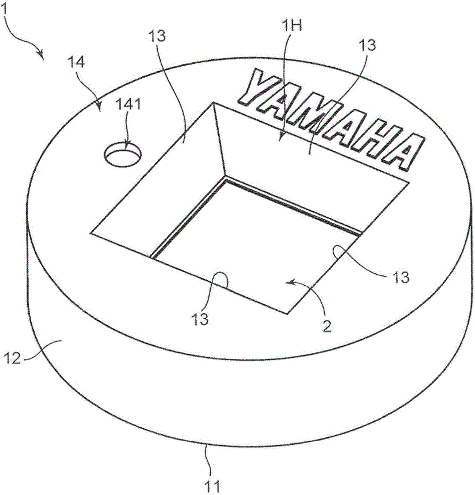
[0068] Container 1 is the same as before based on figure 1 and figure 2 The containers described are the same. Pass the operation hole 141 in advan...

no. 2 approach >

[0095] Figure 15 It is a block diagram schematically showing an object holding device D2 according to the second embodiment. The holding device D2 applies a pressure to the liquid L by using a diaphragm-type dispersing mechanism 3B to generate a liquid flow LC in the through hole 22 . The dispersion mechanism 3B includes a drive mechanism 33 including a working rod 331 and a controller 34 thereof. A part of the bottom wall 11 of the container 1 is formed of an elastically deformable diaphragm 15 (bulging member). The working rod 331 is arranged in a state of being in contact with the diaphragm 15 . In this second embodiment, the operation hole 141 is not used during dispersion, therefore, in Figure 15 Its description is omitted. Other structures are the same as those of the first embodiment.

[0096] The driving mechanism 33 only needs to be able to make the working rod 331 go in and out, for example, a hydraulic mechanism, an air pressure mechanism, a solenoid actuator...

no. 3 approach >

[0102] Figure 17 is a block diagram schematically showing an object holding device D3 according to the third embodiment, Figure 18Ais a plan view of the container used for holding device D3. The holding device D3 is a modified embodiment of the holding device D1 of the first embodiment, and is a holding device having a structure capable of locally dispersing the cell aggregates C carried on the plate 2 .

[0103] The container 1A of the holding device D3 includes a partition wall 16 that divides the closed area CA in the container 1A into four areas. The partition wall 16 is a part that two rectangular flat plates are assembled in a vertical state, and when viewed from above ( Figure 18A ) is in the shape of a cross. The height of the partition wall 16 is equal to the distance between the bottom wall 11 of the container 1A and the plate 2 . By having such a partition wall 16, the closed area CA is divided into the first area RA, the second area RB, the third area RC, an...


PUM


Abstract

An object-holding device comprises a vessel, a plate, and a dispersion mechanism. The vessel stores a liquid and is provided with an upper opening for placing an object in the stored liquid and a bottom wall. The plate has an upper surface and a lower surface. The lower surface is immersed in the liquid at a distance from the bottom wall of the vessel. The plate is provided with one or multiple holding sections, which are disposed on the upper surface side for supporting the object, and through holes, which are formed where the holding sections are disposed and which pass from the upper surface to the lower surface. The dispersion mechanism forms a liquid current that flows in the through holes from the lower surface side to the upper surface side to lift the object supported by the holding sections.

Description

technical field [0001] The present invention relates to a device for holding an object such as a cell aggregate. Background technique [0002] Sometimes it is necessary to keep an object in a container for storing liquid. For example, when the object is a cell aggregate, in order to sort, observe, and culture the cell aggregate, a plate provided with a plurality of cell holding parts may be placed in a cell culture medium stored in a container, And the cell aggregate is held in the holding portion. Patent Document 1 discloses a holding device for holding cells or microspheres for living body experiments on a plate formed with a plurality of through holes as the cell aggregate holding portion. [0003] In the above holding device, it is generally preferable to hold one cell aggregate in one holding portion. However, it is difficult to form such a preferred maintenance state of cell aggregates. That is, when the holding part holds the cell aggregates, the cell suspension c...

Claims


Application Information

Patent Timeline
Patent Type & Authority Applications(China)
IPC IPC(8): C12M1/00C12M3/00
CPCC12M23/12C12M23/34C12M29/14C12M41/40C12M47/04
Inventor 伊藤三郎
Owner YAMAHA MOTOR CO LTD
Why Eureka
Try Eureka