
Support element

A technology for supporting components and pressure parts, applied in the direction of engine components, machines/engines, mechanical equipment, etc., can solve the problems of large dead volume, imprecise timing, non-optimal response characteristics, etc., and achieve short and accurate timing , the effect of short response delay time

Active Publication Date: 2017-03-01
SCHAEFFLER TECH AG & CO KG
View PDF7 Cites 9 Cited by
  • Summary
  • Abstract
  • Description
  • Claims
  • Application Information

AI Technical Summary

Problems solved by technology

A disadvantage of these support elements is that a relatively large dead volume is formed above the cap-shaped element in the pressure piston for receiving the hydraulic medium.
This leads to a non-optimal response behavior of the coupling in the rocker arm and concomitantly to a relatively imprecise timing in the valve drive

Method used


Image

  • Support element

Examples


Embodiment Construction

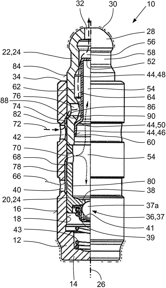
[0021]The hydraulic support element 10 has a substantially pot-shaped housing 12 with a housing bottom 14 and a peripheral side 16 . The housing 12 can be inserted into a receiving bore of a cylinder head (not shown) of the internal combustion engine. The hydraulic channels that supply the hydraulic support element 10 with hydraulic medium open into receiving bores in the cylinder head. In the axially continuous cylindrical bore 18 of the housing 12 is accommodated a piston 24 axially assembled from the working part 20 and the pressure part 22 in a manner capable of moving axially along the longitudinal central axis 26 of the support element 10 . In this case, the working part 20 bears against the pressure part 22 of the piston 24 without play and with axial contact.

[0022] The dome-shaped head 28 of the pressure part 22 of the piston 24 serves as a support for a likewise not shown rocker arm of a valve drive (not shown) of the internal combustion engine. An opening of a ...


PUM


Abstract

The invention relates to a double-flow hydraulic support element (10) for a switchable drag lever of a valve drive of an internal combustion engine. A piston (24) is arranged in an axial bore (18) of the housing (12) of the support element in an axially movable manner, and the piston (24) consists of a hollow cylindrical pressing part (22) and a cup-shaped working part (20). A head (28) of the pressing part (22) is used as a bearing for the drag lever and projects beyond the housing edge (34), and an opening for the flow of a hydraulic medium is formed in the end face (30) of the head (28). The housing (12) has a first passage (40) and a second passage (42) axially spaced from the first passage for the hydraulic medium. The support element (10) has a hydraulic clearance-compensating device (36) with a ball non-return valve (37) for the drag lever. In order to achieve an optimal actuation of the coupling means, a sleeve (44) which is closed on one side is inserted into the pressing part (22); the closed end (52) of the sleeve (44) reaches the region of an outer annular groove (58) in a sealing manner below the dome-shaped head (28) of the pressing part (22); a storage space (54) for supplying the clearance-compensating device (36) with the hydraulic medium is formed radially within and axially outside of the sleeve (44), in the pressing part (22), and in the working part (20) of the piston (24); the storage space (54) is connected to the first passage (40) in the housing (12) via a passage opening (70) in the working part (20); an actuation space (56) formed between the sleeve (44) and the pressing part (22) of the piston (24) for hydraulically supplying the coupling device is connected to the second passage (42) in the housing (12) via a radial passage opening (76) in the pressing part (22); and the volume of the storage space (54) is substantially greater than the volume of the actuation space (56).

Description

technical field [0001] The invention relates to a two-flow hydraulic support element for a switchable rocker arm of a valve drive of an internal combustion engine, which has a pot-type housing which can be inserted into a cylinder head of an internal combustion engine, wherein , in the axial hole of the housing, coaxially with the longitudinal center axis of the support element, a piston is arranged in an axially movable manner, wherein the piston consists of a hollow cylinder-shaped pressure part and an axially coupled Pot-shaped working part, wherein at least one head of the pressure part of the piston serves as a support for the switchable rocker arm and protrudes axially beyond the housing edge, wherein the through-flow pair is used for the switchable The opening of the hydraulic medium in the rocker arm which can be acted upon by the hydraulically actuated coupling device is formed in the end side of the head of the piston, wherein the housing has a first radial opening f...

Claims


Application Information

Patent Timeline
Patent Type & Authority Applications(China)
IPC IPC(8): F01L1/24F01L13/00
CPCF01L1/2405F01L13/0005F01L1/14F01L1/46F01L2001/2444
Inventor 于尔根·克雷奇默彼得·赛勒沃尔夫冈·克里斯特根米夏埃尔·库格勒约亨·托瓦尔马克斯·舍费尔
Owner SCHAEFFLER TECH AG & CO KG
Learn More