Hydrodynamic bearings and motor vehicles having such hydrodynamic bearings

A bearing and hydraulic technology, applied in the field of hydraulic bearings, can solve problems such as unrealizable, insufficient, lack of power and/or dynamic characteristics, etc., and achieve the effect of favorable production and simple structure

Active Publication Date: 2020-03-27
CONTITECH VIBRATION CONTROL
View PDF3 Cites 0 Cited by
  • Summary
  • Abstract
  • Description
  • Claims
  • Application Information

AI Technical Summary

Problems solved by technology

[0024] A disadvantage of known hydrodynamic bearings is that electromagnetic linear actuators generally do not have the necessary power and / or dynamics to use a particularly bending-resistant control diaphragm and / or a particularly bending-resistant support spring such as Desirably "soft" turn-on of the hydrodynamic bearing
Also note that only a limited construction space is available for the linear actuator in a hydrodynamic bearing
That is to say, when it is determined that the forces and / or dynamics of a linear actuator are insufficient and therefore a more efficient linear actuator is required where appropriate, this is mostly not achievable since the available construction space is used Known electromagnetic linear actuators are insufficient

Method used


Image

  • Hydrodynamic bearings and motor vehicles having such hydrodynamic bearings
  • Hydrodynamic bearings and motor vehicles having such hydrodynamic bearings

Examples


Embodiment Construction

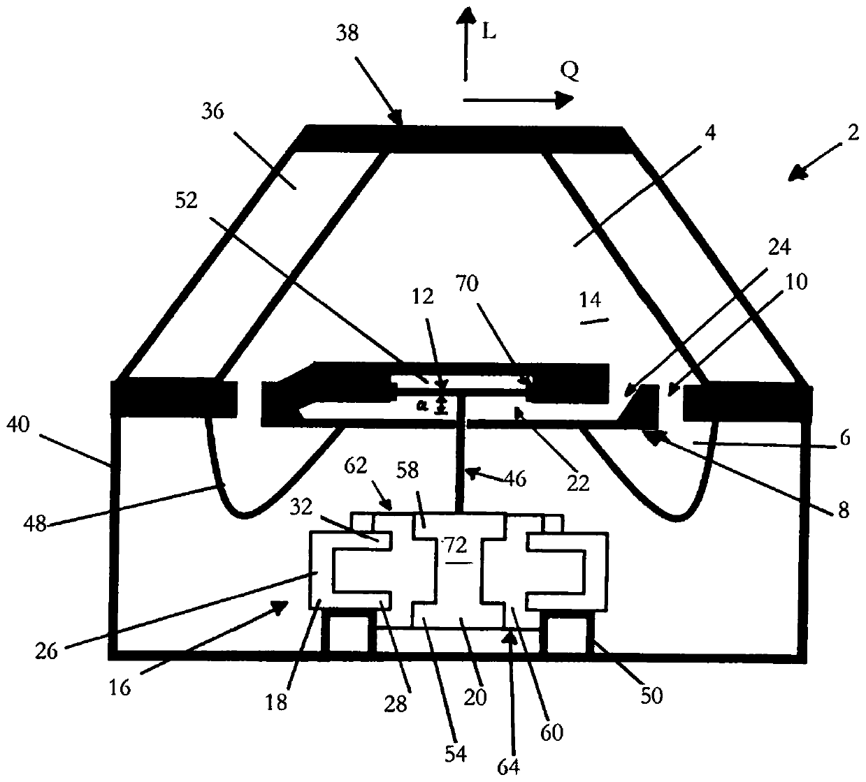
[0045] From figure 1 A hydrodynamic bearing 2 can be seen. The hydrodynamic bearing 2 includes a support spring 36 configured as a rubber element. The supporting spring 36 is generally formed as a hollow body, wherein the upper side of the supporting spring 36 has a cover 38 . A connecting element (not shown) is usually arranged on the cover part 38 for fastening the motor. In a simple embodiment, the connecting element is a threaded bolt which can be screwed to the motor. The partition wall 8 adjoins the underside of the support spring 36 . The working chamber 4 is formed between the support spring 36 , the cover 38 and the partition wall 8 . The working chamber 4 is filled with a hydraulic fluid. Here, the hydraulic fluid preferably refers to a mixture of oil and water. The hollow cylindrical base housing 40 adjoins in the longitudinal direction L below the partition wall 8 , the interior of which is divided by a flexible partition 48 . This separator 48 is also refer...


PUM


Abstract

The invention relates to a hydrodynamic bearing (2) having: a supporting spring (36); a working chamber (4) at least partially surrounded by the supporting spring (36), the working chamber being filled with hydraulic fluid; a control diaphragm (12 ), the control diaphragm is formed for changing the working chamber volume of the working chamber (4); and an electromagnetic actuator (16) for deflecting the control diaphragm (12), wherein the actuator (16) Comprising a stator (18) and an armature (20) movable in the longitudinal direction L of the stator (18), the armature (20) is mechanically connected to the control diaphragm (12), the stator (18) has a ferromagnetic material manufactured stator guide element (26) having an upper stator collar (32) extending in the transverse direction Q of the stator (18) and in the transverse direction Q of the stator (18) Extended lower stator collar (28), the armature (20) has an armature guide element (72) made of ferromagnetic material, the armature guide element (72) has a The upper armature collar (58) and the lower armature collar (54) extending in the transverse direction Q of the stator (18), the upper stator collar (32) and the upper armature collar (58) face each other, And the lower stator collar (28) and the lower armature collar (54) face each other, wherein the control diaphragm (12) is formed in its deflection direction for maximum deflection a, and these face each other accordingly, The upper and / or lower collars (32, 58 or 28, 54) partially overlap over an overlapping length u in the longitudinal direction L of the stator (18) such that the ratio of the overlapping length u to the maximum deflection a is between 0.1 and 1.5 between. Furthermore, the invention relates to a motor vehicle with a corresponding hydrodynamic bearing (2).

Description

technical field [0001] The invention relates to a hydrodynamic bearing having: a support spring; a working chamber at least partially surrounded by the support spring, the working chamber being filled with a hydraulic fluid; a control diaphragm forming for changing the working chamber volume of the working chamber; and an electromagnetic actuator for deflecting the control diaphragm, wherein the actuator comprises a stator and an armature movable in the longitudinal direction of the stator, The armature is mechanically connected to the control diaphragm, the stator has a stator guide element made of ferromagnetic material, the stator guide element has an upper stator collar extending in the transverse direction of the stator and in the transverse direction of the stator A lower stator collar extending upward, the armature has an armature guide element made of ferromagnetic material, the armature guide element has an upper armature collar extending in the transverse direction o...

Claims


Application Information

Patent Timeline
Patent Type & Authority Patents(China)
IPC IPC(8): F16F13/26
CPCF16F13/264F16F13/085F16F13/30
Inventor 马克斯·韦哈恩罗伯特·延德雅恩彼得·马林费尔德
Owner CONTITECH VIBRATION CONTROL
Why Eureka
Try Eureka