Chemical gas and liquid mixing reactor with gas recycling device

A gas recovery, gas-liquid mixing technology, applied in chemical methods, chemical/physical/physical-chemical stationary reactors, chemical instruments and methods for reacting liquids with gaseous media, etc., can solve the problem of large consumption of raw materials and low efficiency , long reaction time for returning to school, etc., to reduce production costs, improve mixing efficiency, and reduce occupied space.

Inactive Publication Date: 2017-03-08
ZHENGZHOU AIMOFU INFORMATION TECH CO LTD
View PDF0 Cites 18 Cited by
  • Summary
  • Abstract
  • Description
  • Claims
  • Application Information

AI Technical Summary

Problems solved by technology

[0002] There are a large number of gas-liquid reactions in the chemical industry, such as industrial waste gas treatment, catalytic hydrogenation, amination reactions, etc. Commonly used gas-liquid reaction devices include absorption towers, venturi tubes, jet injectors, etc. The liquid in the absorption tower is sprayed upwards from the top of the tower, and the gas is mixed upwards from the bottom to achieve gas-liquid mixing, that is, a chemical reaction occurs. The jet injector uses the jet port to form a negative pressure to suck the gas, thereby realizing gas-liquid mixing; However, the gas-liquid mixing reaction device adopting this structure has poor mixing effect between gas and liquid, and cannot realize sufficient mixing of gas and liquid. Therefore, it is particularly necessary to provide a gas-liquid mixing reaction device that can fully mix the gas-liquid materials

Method used


Image

  • Chemical gas and liquid mixing reactor with gas recycling device
  • Chemical gas and liquid mixing reactor with gas recycling device

Examples


Embodiment Construction

[0015] The following will clearly and completely describe the technical solutions in the embodiments of the present invention with reference to the accompanying drawings in the embodiments of the present invention. Obviously, the described embodiments are only some, not all, embodiments of the present invention. Based on the embodiments of the present invention, all other embodiments obtained by persons of ordinary skill in the art without making creative efforts belong to the protection scope of the present invention.

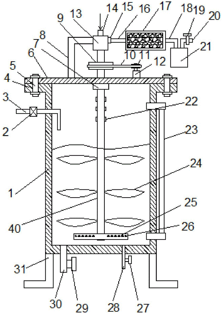
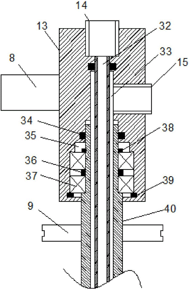
[0016] see Figure 1-2 , a chemical gas-liquid mixing reactor with a gas recovery device, comprising a tank body 1 and an upper cover 6, the outer periphery of the upper end of the tank body 1 is provided with a ring-shaped extension 4, and the upper cover 6 is fixed by a plurality of bolts 5 On the Yanbian 3 of the tank body 1; the upper left end of the tank body 1 is provided with a liquid inlet pipe 3 with an electromagnetic switch valve 2, and an external ...


PUM


Abstract

The invention discloses a chemical gas and liquid mixing reactor with a gas recycling device. The chemical gas and liquid mixing reactor comprises a tank and an upper cover. An annular extension edge is arranged on the periphery of the upper end of the tank, and the upper cover is fixed onto the extension edge of the tank by the aid of a plurality of bolts; a liquid inlet pipe with an electromagnetic switch valve is arranged at the upper end of the left side of the tank, and an external liquid pressure gauge is arranged on the right side of the tank; a sampling pipe with a sampling pipe valve and a discharge pipe with a discharge pipe valve are arranged in the middle of the lower end of the tank, and a plurality of support legs are arranged at the edge of the lower end of the tank; an inverted-L-shaped mounting frame is arranged at the upper end of the upper cover, and a rotary connector is arranged on the mounting frame. The chemical gas and liquid mixing reactor has the advantages that the chemical gas and liquid mixing reactor is reasonable in structural design and is provided with the rotary connector, so that a rotary shaft can rotate while the chemical gas and liquid mixing reactor is filled with chemical gas, and the production cost can be reduced; the rotary shaft is provided with chemical gas inlet and outlet channels, and accordingly occupied spaces can be reduced.

Description

technical field [0001] The invention relates to chemical equipment, in particular to a chemical gas-liquid mixing reactor with a gas recovery device. Background technique [0002] There are a large number of gas-liquid reactions in the chemical industry, such as the treatment of industrial waste gas, catalytic hydrogenation, amination reactions, etc. The commonly used gas-liquid reaction devices include absorption towers, venturi tubes, jet injectors, etc. The liquid in the absorption tower is sprayed upward from the top of the tower, and the gas is mixed upward from the bottom to realize the gas-liquid mixing, that is, a chemical reaction occurs. The jet injector uses the jet port to form a negative pressure to suck the gas, so as to realize the gas-liquid mixing; However, the gas-liquid mixing reaction device adopting this structure has poor mixing effect between gas and liquid, and cannot realize sufficient mixing of gas and liquid. Therefore, it is particularly necessar...

Claims


Application Information

Patent Timeline
Patent Type & Authority Applications(China)
IPC IPC(8): B01J10/00B01J19/18
CPCB01J10/00B01J19/0053B01J19/18
Inventor 不公告发明人
Owner ZHENGZHOU AIMOFU INFORMATION TECH CO LTD
Why Eureka
Try Eureka