
Spinning device and spinning molding method for cylindrical material

A spinning and cylindrical technology, which is applied to the spinning device of cylindrical materials and the field of spinning, can solve the problems of falling off, increased operation cycle time, deformation of the flange-shaped protruding edge 11, etc. Improve work efficiency and improve retention effect

Active Publication Date: 2018-09-11
NIHON SPINDLE MFG CO LTD
View PDF2 Cites 0 Cited by
  • Summary
  • Abstract
  • Description
  • Claims
  • Application Information

AI Technical Summary

Problems solved by technology

[0008] However, depending on the cylindrical material to be spin-formed, it may be necessary to increase the tension applied in the axial direction of the cylindrical material 10, and when a large tension acts in the axial direction, there is a flange-shaped protruding edge. The problem that the part 11 is deformed and falls off from the tension applying mechanism 40
[0009] In addition, it is required that the fork-shaped jig for releasing the cylindrical material 10 from the mandrel 20 by moving the reduced diameter cylindrical material 10 toward the front end side of the mandrel 20 should not interfere with the rollers. 30 operation in the way of interference, therefore, there is a problem that the operation cycle time increases

Method used


Image

  • Spinning device and spinning molding method for cylindrical material
  • Spinning device and spinning molding method for cylindrical material
  • Spinning device and spinning molding method for cylindrical material

Examples


Embodiment Construction

[0026] Hereinafter, embodiments of a spinning device and a spinning method for a cylindrical material according to the present invention will be described with reference to the drawings.

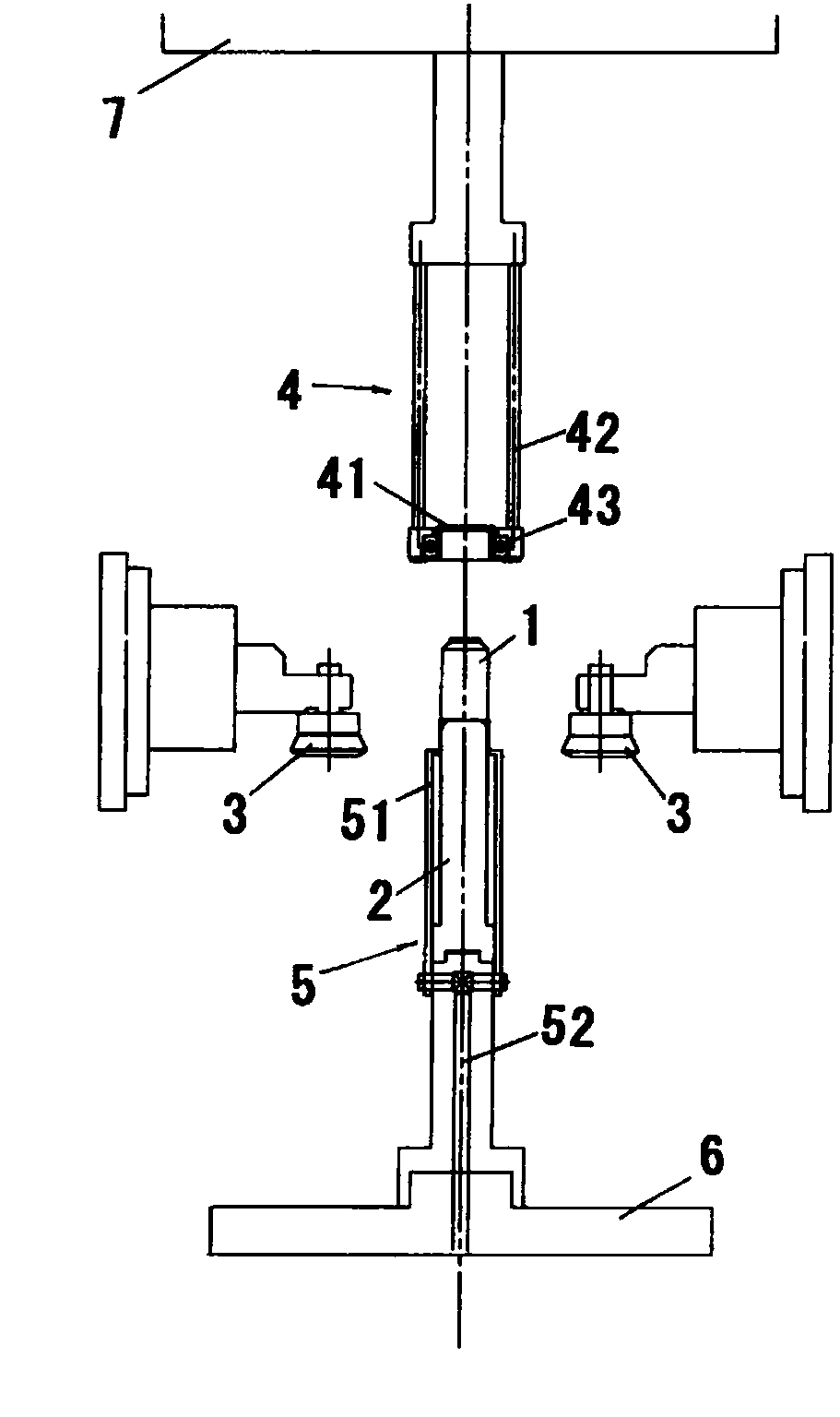
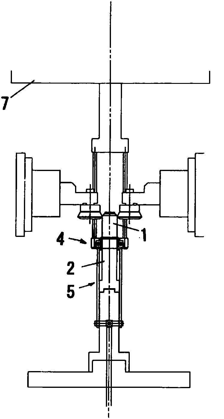
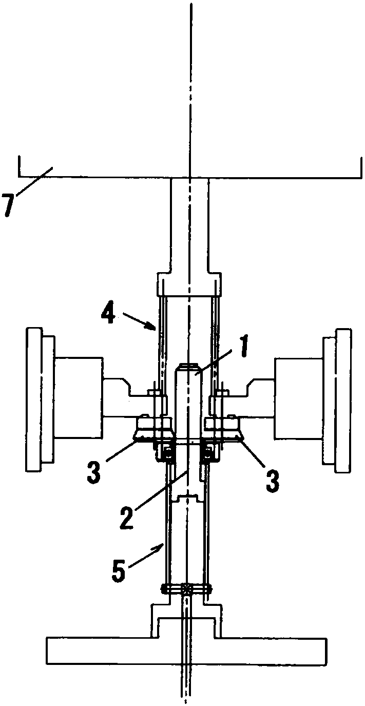
[0027] Figure 1(a) to Figure 2(b) An example of the spinning method using the spinning device of the cylindrical material of the present invention is shown in .

[0028] In this spinning device for cylindrical materials, a metal cylindrical material 1 is placed on a mandrel 2, and tension is applied to the axial direction of the cylindrical material 1 while the roller 3 is pressed against the cylindrical material from the outer peripheral side. 1 to perform diameter reducing extrusion processing, thereby realizing elongation and thinning of the cylindrical material 1, the spinning device is equipped with: a tension imparting mechanism 4, which passes through the protruding edge formed at the open end of the cylindrical material 1 part 11 applies tension to the axial direction of cylindrica...


PUM


Abstract

The present invention provides a cylindrical material spinning device which is formed at a cylindrical material protruding edge portion and will not deform and fall off from a tension giving mechanism even a larger tension is put in an axial direction of the cylindrical material and a spinning method. The spinning device has the tension giving mechanism (4) which applies the tension to the axial direction of the cylindrical material (1) through the protruding edge portion (11) formed at an opening end portion of the cylindrical material (1); and a supporting mechanism (5), wherein the protruding edge portion (11) of the cylindrical material (1) is clamped between the supporting mechanism and the tension giving mechanism (4), and ironing is performed while the tension is applied to the axial direction of the cylindrical material (1) when the protruding edge portion (11) of the cylindrical material (1) is clamped between the tension giving mechanism (4) and the supporting mechanism (5).

Description

[0001] This application claims priority based on Japanese Patent Application No. 2015-170074 filed on August 31, 2015. The entire contents of this Japanese application are incorporated herein by reference. technical field [0002] The invention relates to a spinning device and a spinning forming method for a cylindrical material. Background technique [0003] Conventionally, for manufacturing rollers of printers and copiers, toner cartridges, liners of thermos bottles, etc., a spin forming method using a spinning apparatus has been widely used (for example, refer to Patent Document 1). [0004] like image 3 As shown, the spinning method based on this spinning device is to fit a metal cylindrical material 10 on a mandrel 20 and make the tension imparting mechanism 40 protrude through the open end formed on the cylindrical material 10 . The edge portion 11 applies tension to the axial direction of the cylindrical material 10, and the roller 30 presses the cylindrical materia...

Claims


Application Information

Patent Timeline
Patent Type & Authority Patents(China)
IPC IPC(8): B21D22/16
CPCB21D22/16
Inventor 桧桓孝二
Owner NIHON SPINDLE MFG CO LTD
Learn More