
Fixture for grinding pressure casting

A technology of die-casting parts and fixtures, which is applied in the direction of grinding workpiece supports, etc., can solve problems such as inability to effectively ensure grinding consistency and standardized operations, poor labor protection effects, and affect product quality, so as to improve work efficiency and grinding accuracy , easy to operate, and simplify the grinding process

Active Publication Date: 2017-03-08
GUANGZHOU INST OF ADVANCED TECH CHINESE ACAD OF SCI +1
View PDF5 Cites 3 Cited by
  • Summary
  • Abstract
  • Description
  • Claims
  • Application Information

AI Technical Summary

Problems solved by technology

[0002] At present, mechanical production and processing often require grinding of products. The usual method is that the operator directly grinds the workpiece with his hand, especially for workpieces with large volume and complex shapes, which cannot effectively ensure the consistency and standardized operation of grinding, and The labor protection effect is not good, thus affecting the quality of the product
At present, the existing grinding fixtures for die castings generally need to be turned manually to adjust the direction, which is time-consuming and labor-intensive.

Method used


Image

  • Fixture for grinding pressure casting
  • Fixture for grinding pressure casting
  • Fixture for grinding pressure casting

Examples


Embodiment Construction

[0023] The technical solutions in the embodiments of the present invention will be clearly and completely described below in conjunction with the accompanying drawings in the embodiments of the present invention. Obviously, the described embodiments are only a part of the embodiments of the present invention, rather than all the embodiments. Based on the embodiments of the present invention, all other embodiments obtained by those of ordinary skill in the art without creative work shall fall within the protection scope of the present invention.

[0024] It should be noted that all the directional indications (such as up, down, left, right, front, back...) in the embodiments of the present invention are only used to explain the difference between components in a specific posture (as shown in the accompanying drawings). If the relative positional relationship, movement situation, etc. change, the directional indication will change accordingly. In addition, descriptions related to "...


PUM


Abstract

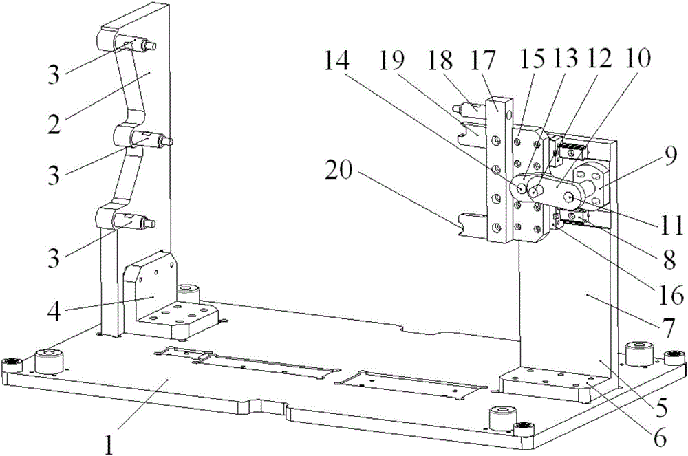
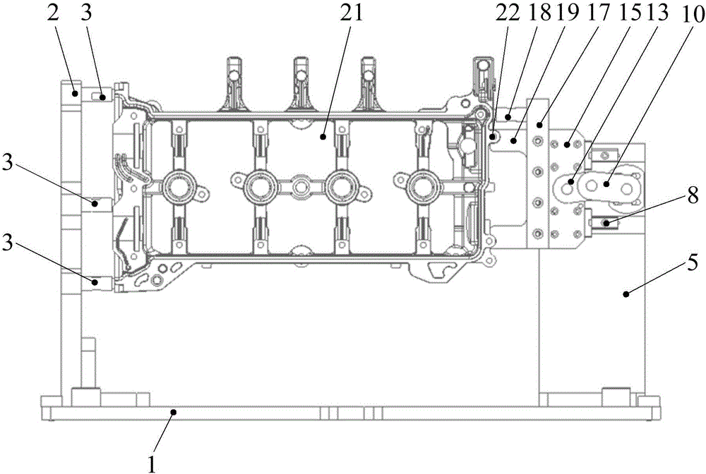
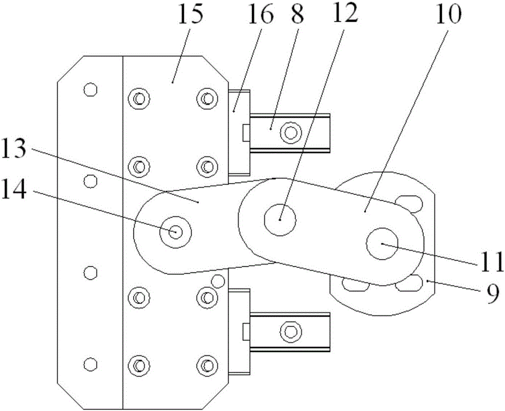
The invention discloses a fixture for grinding a pressure casting. The fixture comprises a bottom plate; the bottom plate is vertically provided with a first side plate and a second side plate; the first side plate is horizontally and convexly provided with a first cylindrical pin towards the second side plate; the first cylindrical pin is matched with a round hole in one end surface of the pressure casting; the second side plate is provided with a locking mechanism comprising a first connecting plate, a second connecting plate, a push plate and a clamping plate; one end of the first connecting plate is connected to the second side plate through a first screw, and the other end of the first connecting plate is connected to one end of the second connecting plate through a movable screw; the other end of the second connecting plate is connected to the push plate through a second screw; the surface, close to the second side plate, of the push plate is fixedly provided with a slide block; the second side plate is horizontally provided with a guide rail; the slide block is arranged on the guide rail; the clamping plate is fixedly arranged on the push plate; the clamping plate is horizontally and convexly provided with a second cylindrical pin and a clamping block towards the first side plate; and the second cylindrical pin and the clamping block are matched with a round hole and a boss which are formed in the other end surface of the pressure casting. The fixture disclosed by the invention is precise in location, simple in clamping, suitable for large-scale processing of products and capable of increasing the production efficiency.

Description

Technical field [0001] The invention relates to a clamp device for grinding mechanical parts, in particular to a clamp for grinding die castings. Background technique [0002] At present, mechanical production and processing often need to polish the product. The usual method is that the operator holds the workpiece directly to polish, especially for the large and complex shape of the workpiece, which cannot effectively guarantee the consistency and standardized operation of the polishing. The labor protection effect is not good, thus affecting the quality of the product. The existing grinding fixtures for die castings generally need to be manually turned to adjust the direction, which is time-consuming and labor-intensive. [0003] Therefore, it is necessary to provide a better grinding clamp to solve the above problems. Summary of the invention [0004] In view of the problems in the prior art, the present invention provides a fixture for die casting grinding that is suitable for...

Claims


Application Information

Patent Timeline
Patent Type & Authority Applications(China)
IPC IPC(8): B24B41/06
CPCB24B41/06
Inventor 张弓宋雅伦王卫军侯至丞顾星徐征
Owner GUANGZHOU INST OF ADVANCED TECH CHINESE ACAD OF SCI
Learn More