Cache queue logic control method for cod detection process

A cache queue and logic control technology, applied in the field of cache queue logic control, can solve the problems of deviation in analysis results, inability to obtain analysis results, and no analysis results, saving reagents, improving measurement efficiency, and prolonging equipment life.

Active Publication Date: 2018-07-20
SHANGHAI BAOSIGHT SOFTWARE CO LTD
View PDF5 Cites 0 Cited by
  • Summary
  • Abstract
  • Description
  • Claims
  • Application Information

AI Technical Summary

Problems solved by technology

[0009] image 3 Indicates the sewage discharge situation of a certain site within 24 hours. A total of 12 water sample analyzes were carried out in one day. Among them, the water samples analyzed for 3 times during the frequent stop / drain switching period were the above due to the characteristics of the sampling system’s water collection delay. The sewage discharged for the second time, the analysis result has a deviation (represented by the grid filled triangle), and the analysis result is invalid
During the 5th analysis, no sewage was discharged, the equipment was empty (indicated by a white triangle), and no analysis results were produced.
[0013] Figure 5 Indicates the sewage discharge situation of a site within 24 hours. A total of 14 water sample analyzes were carried out in one day, of which 5 analyzes were due to frequent stop / drain switching (indicated by white triangles in the figure), and the drainage time was less than 50 minutes. When the stop command is received during the running analysis phase, the analysis stops immediately, and the analysis results cannot be obtained, which wastes a lot of reagents
Due to the time-delay characteristics of the sampling system, the analysis of the water samples for the 3 times was the sewage discharged last time, the analysis results were biased (represented by the grid filled triangles), and the analysis results were invalid

Method used


Image

  • Cache queue logic control method for cod detection process
  • Cache queue logic control method for cod detection process
  • Cache queue logic control method for cod detection process

Examples


Embodiment Construction

[0057] The present invention will be described in detail below in conjunction with specific embodiments. The following examples will help those skilled in the art to further understand the present invention, but do not limit the present invention in any form. It should be noted that those skilled in the art can make several modifications and improvements without departing from the concept of the present invention. These all belong to the protection scope of the present invention.

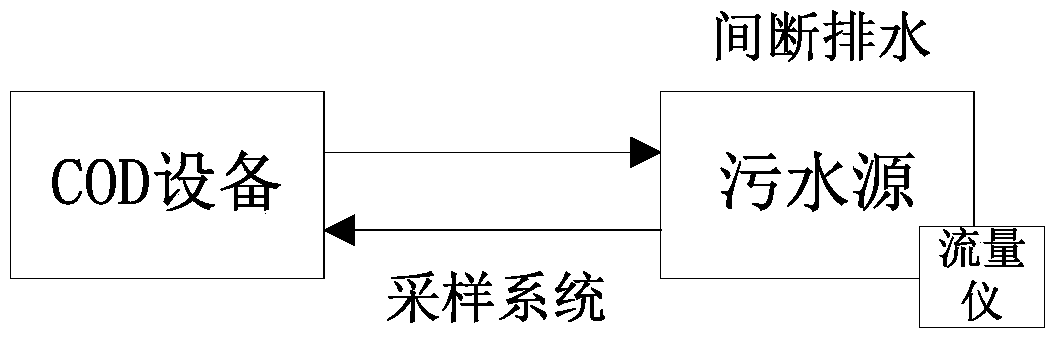
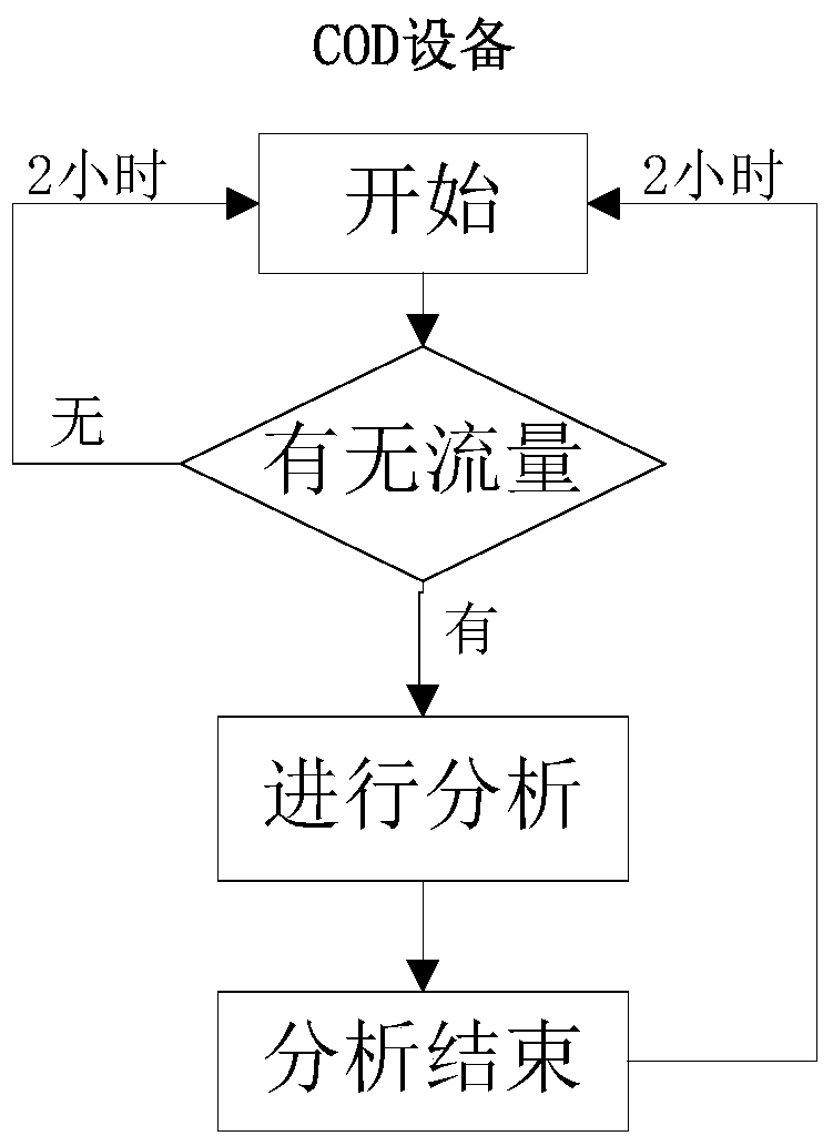
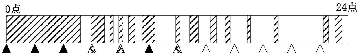
[0058] Through the analysis and research of the COD measurement process and the intermittent discharge characteristics of pollution sources, a buffer queue and two operating status detections are added to the sampling process: drainage buffer detection and analysis interval detection.

[0059] The drainage cache queue is used to store sewage source stop / drainage information. During the operation of the system, when the sewage source switches from the water cut state to the drainage state, the syst...


PUM


Abstract

The invention provides a buffer queue logic control method of a COD detection process. The buffer queue logic control method comprises: (1) determining whether the state information recorded by a water draining buffer queue is the water draining state information, and entering a step (3) if the determining result of the step (1) is true; (3) determining whether the water draining buffer detection result is the true, and entering a step (4) if the determining result of the step (3) is the true; (4) determining whether an analysis interval detection result is true, and entering a step (5) if the determining result of the step (4) is true; and (5) sending a measurement starting command to a COD detection device, and recording the measurement starting command sending time. With the buffer queue logic control method of the present invention, how to rationally and effectively perform the logic control on the COD measurement process is solved, such that the ineffective measurement is reduced, the precious reagent is saved, and the number of the effective measurement values is increased so as to improve the measurement efficiency of the polluted water source.

Description

technical field [0001] The invention relates to the detection of chemical oxygen demand (COD), in particular to a buffer queue logic control method of the COD detection process. The method can be widely used in logic control of COD equipment when polluted water sources are discharged non-sustainably. Background technique [0002] Chemical oxygen demand (COD) reflects the content level of oxygen-consuming organic pollutants in water samples, and is an important monitoring item in the monitoring of oxygen-consuming organic pollutants in water bodies. For the treatment of sewage, our country stipulates that potassium dichromate method is used, and the measured value is called chemical oxygen demand. That is, under the condition of strong acid and heating, the amount of oxidant consumed when the water sample is treated with excess potassium dichromate, expressed in oxygen (mg / L). The potassium dichromate method is used to measure COD, which is easy to operate and has good repr...

Claims


Application Information

Patent Timeline
Patent Type & Authority Patents(China)
IPC IPC(8): G01N35/00
Inventor 薛如冰王瑞
Owner SHANGHAI BAOSIGHT SOFTWARE CO LTD
Why Eureka
Try Eureka