

electronic components
A technology of electronic components and ground electrodes, which is applied to components of fixed capacitors, electrical components, and components of transformers/inductors, etc., can solve the problems of reduced signal quality, poor signal transmission characteristics, etc. The effect of reducing and preventing movement
- Summary
- Abstract
- Description
- Claims
- Application Information
AI Technical Summary
Problems solved by technology
Method used
Image

Examples
no. 1 approach
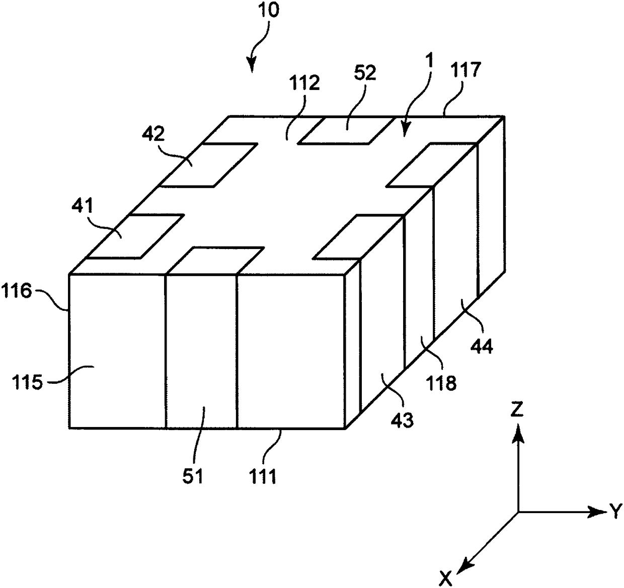
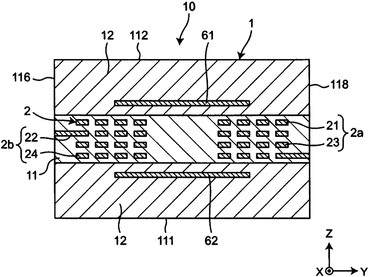
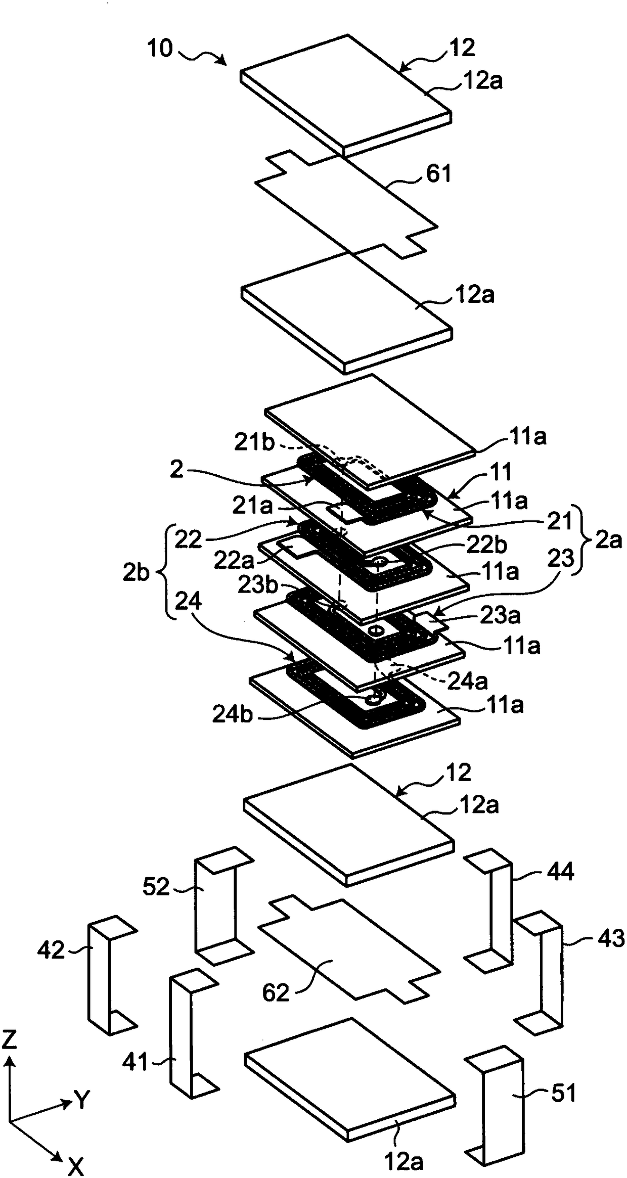
[0052] figure 1 It is a perspective view which shows the electronic component which concerns on 1st Embodiment of this invention. figure 2 is a cross-sectional view of an electronic component. image 3 It is an exploded perspective view of an electronic part. Such as figure 1 , figure 2 ,as well as image 3 As shown, the electronic component 10 has: a laminated body 1, a common mode choke coil 2 disposed in the laminated body 1, first and second ground electrodes 61, 62 disposed in the laminated body 1, and the first and second The two ground electrodes 61, 62 are connected to the first and second ground terminals 51, 52.
[0053] The electronic component 10 is electrically connected to the mounting substrate. The electronic component 10 is mounted, for example, in electronic devices such as personal computers, DVD players, digital cameras, TVs, mobile phones, and automotive electronic devices.
[0054] The laminated body 1 includes a plurality of laminated insulati...
no. 2 approach
[0091] Figure 5A It is a YZ cross-sectional view showing the second embodiment of the electronic component of the present invention. Figure 5B It is an XY sectional view showing the second embodiment of the electronic component of the present invention. The second embodiment is different from the first embodiment in the configuration of the first and second ground electrodes. Only this different configuration will be described below. However, in the second embodiment, since the same reference numerals as those in the first embodiment denote the same configurations as in the first embodiment, description thereof will be omitted.
[0092] Such as Figure 5A and Figure 5B As shown, in the electronic component 10A of the second embodiment, the first ground electrode 61A and the second ground electrode 62A overlap the primary coil 2a and the secondary coil 2b when viewed from the stacking direction, and do not overlap with the inner diameter portion of the primary coil 2a an...
no. 3 approach
[0096] Figure 6A It is a YZ cross-sectional view showing the third embodiment of the electronic component of the present invention. Figure 6B It is an XY cross-sectional view showing a third embodiment of the electronic component of the present invention. The third embodiment is different from the second embodiment in the configuration of the first and second ground electrodes 61B, 62B. Only this different configuration will be described below. However, in the third embodiment, the same reference numerals as those in the second embodiment denote the same configurations as in the second embodiment, and therefore description thereof will be omitted.
[0097] Such as Figure 6A and Figure 6B As shown, in the electronic component 10B of the third embodiment, the first ground electrode 61B and the second ground electrode 62B respectively have patterns similar to those of the opposing coils of the primary coil 2 a and the secondary coil 2 b when viewed from the stacking direc...
PUM
 Abstract
Description
Claims
Application Information