A maintenance-free slip ring with high current and high power

A high-power, maintenance-free technology, applied in the direction of circuits, current collectors, electrical components, etc., can solve the problems of high cost of use and poor reliability, and achieve the effect of reducing raw material costs, cost reduction, and good dispersion performance

Active Publication Date: 2019-09-20
LINYI HAINA ELECTRONICS
View PDF12 Cites 0 Cited by
  • Summary
  • Abstract
  • Description
  • Claims
  • Application Information

AI Technical Summary

Problems solved by technology

[0004] The purpose of the present invention is to solve the technical problems of poor reliability and high cost of use in the prior art, and provide a maintenance-free slip ring with high current and high power to overcome the deficiencies of the prior art

Method used


Image

  • A maintenance-free slip ring with high current and high power

Examples


Embodiment 1

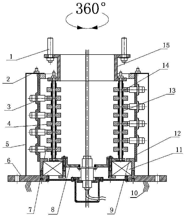
[0019] according to figure 1 , the present invention includes a mounting plate 6; the top surface of the mounting plate 6 is fixedly provided with a bearing seat 11;

[0020] The inner ring of the bearing seat 11 is tightly connected with the slip ring 8, and the top surface of the slip ring 8 is fixed with a column 14; the column The top of 14 is tightly connected with the rotating ring 15; the top of the rotating ring 15 is provided with a shift fork 1; the column 14 is evenly provided with a number of conductive rings 4 fixedly connected to each other through the bracket 13;

[0021] The outer ring and column of the bearing housing 11 12 fixed connections; the uprights The top of 12 is fixedly connected with protective cover 5 by fastening bolt 2; 12 is evenly provided with a number of brushes 3, and the inner end of the brush 3 is movably plugged with a conductive column 7; the conductive column 7 is elastically connected to the brush 3 through a spring; the con...

Embodiment 2

[0025] The conductive ring described in embodiment 1 is prepared according to the following process:

[0026] First put copper into a vacuum induction melting furnace, heat it to 300°C, then add aluminum, zirconium, nickel, manganese, vanadium, titanium, yttrium and cerium for melting, the melting temperature is 1220°C, the melting time is 20min, and then argon Protective injection molding, the argon protection pressure is 0.9MPa, the nozzle diameter is 3mm, the oblique angle is 37°, the eccentricity is 30mm, and the melt mass flow rate is 10kg / min; the injection-molded alloy material is put into the hot extrusion Hot extrusion in a press, extrusion temperature 300°C, pressure 300MP, heat preservation and pressing for 4 hours; cool down to room temperature, then perform cold pressing at a pressure of 70MP for 2 times, each pressing for 2 hours; finally use a lathe for surface treatment to obtain the product. The mass ratio of copper, aluminum, zirconium, nickel, manganese, van...

Embodiment 3

[0028] A conductive ring, which is prepared according to the following process:

[0029] First put copper into a vacuum induction melting furnace and heat it to 300°C, then add aluminum, zirconium, nickel, manganese, vanadium, titanium, yttrium and cerium for melting, the melting temperature is 1230°C, the melting time is 20min, and then argon Protective injection molding, the argon protection pressure is 0.9MPa, the nozzle diameter is 3mm, the oblique angle is 37°, the eccentricity is 30mm, and the melt mass flow rate is 10kg / min; the injection-molded alloy material is put into the hot extrusion Hot extrusion in a press, extrusion temperature 300°C, pressure 300MP, heat preservation and pressing for 4h; cool down to room temperature, then perform cold pressing at a pressure of 70MP twice, each pressing for 2h; finally use a lathe for surface treatment to obtain the product. The mass ratio of copper, aluminum, zirconium, nickel, manganese, vanadium, titanium, yttrium and ceriu...


PUM


Abstract

The invention discloses a high-current and high-power maintenance-free slip ring. The high-current and high-power maintenance-free slip ring comprises a mounting plate, wherein a bearing pedestal is arranged on the top surface of the mounting plate; an inner ring of the bearing pedestal is connected with the slip ring; a stand column I is arranged on the top surface of the slip ring; the top end of the stand column I is connected with a rotating ring; the stand column I is provided with conductive rings; an outer ring of the bearing pedestal is connected with a stand column II; the top end of the stand column II is connected with a protective cover; the stand column II is provided with electric brushes with conductive columns; the conductive columns are elastically connected with the corresponding electric brushes through springs; the conductive columns are connected with the corresponding conductive rings in a fitting manner; a dust holding groove is formed in the connecting place between the stand column II and the outer ring of the bearing pedestal; and the corresponding fitting places between the conductive columns and the conductive rings are vertically corresponding to the dust holding groove. The stand column I is driven by a shifting fork to rotate so as to enable the conductive rings and the corresponding conductive columns on the electric brushes to be in friction constantly to realize electric connection; powder generated in the friction can naturally fall into the dust holding groove without being cleaned, so that the maintenance-free effect is realized; and in addition, the cost is effectively lowered while the reliability is high.

Description

technical field [0001] The invention belongs to the technical field of electrical connector slip rings, in particular to a maintenance-free slip ring with high current and high power. Background technique [0002] In the electrical connection system, the slip ring technology is widely used, and the traditional high-current and high-power slip ring adopts the contact form of the sliding friction electrical contact pair, and the sliding friction between the electrical contact materials will inevitably cause a large amount of grinding powder. During the process, it is easy to backlog in the conductive place and cannot be discharged, which will cause the insulation resistance of the slip ring to increase, resulting in the failure of the electrical connection of the slip ring and poor reliability; moreover, a large amount of powder generated needs to be maintained irregularly according to the usage conditions, resulting in slip rings. Increase in ring usage costs. [0003] The f...

Claims


Application Information

Patent Timeline
Patent Type & Authority Patents(China)
IPC IPC(8): H01R39/08H01R39/14
Inventor 卞磊程晓华
Owner LINYI HAINA ELECTRONICS
Why Eureka
Try Eureka