A lens propulsion actuator

A technology for actuators and lenses, applied in the field of electric servo systems, can solve the problems of no technology disclosure in Solution 3, and achieve the effects of compact structure, convenient assembly, and easy processing

Active Publication Date: 2019-01-15
BEIJING AUTOMATION CONTROL EQUIP INST
View PDF5 Cites 0 Cited by
  • Summary
  • Abstract
  • Description
  • Claims
  • Application Information

AI Technical Summary

Problems solved by technology

[0005] Scheme 3 requires the use of a ratchet mechanism, which is more complicated in design, but it uses a mechanical structure to prevent reversal, has higher reliability, and the return error is controllable. However, no specific technology for Scheme 3 has been disclosed so far.

Method used


Image

  • A lens propulsion actuator
  • A lens propulsion actuator
  • A lens propulsion actuator

Examples


Embodiment Construction

[0024] The technical solution of the present invention will be described in detail below in conjunction with the accompanying drawings and specific embodiments.

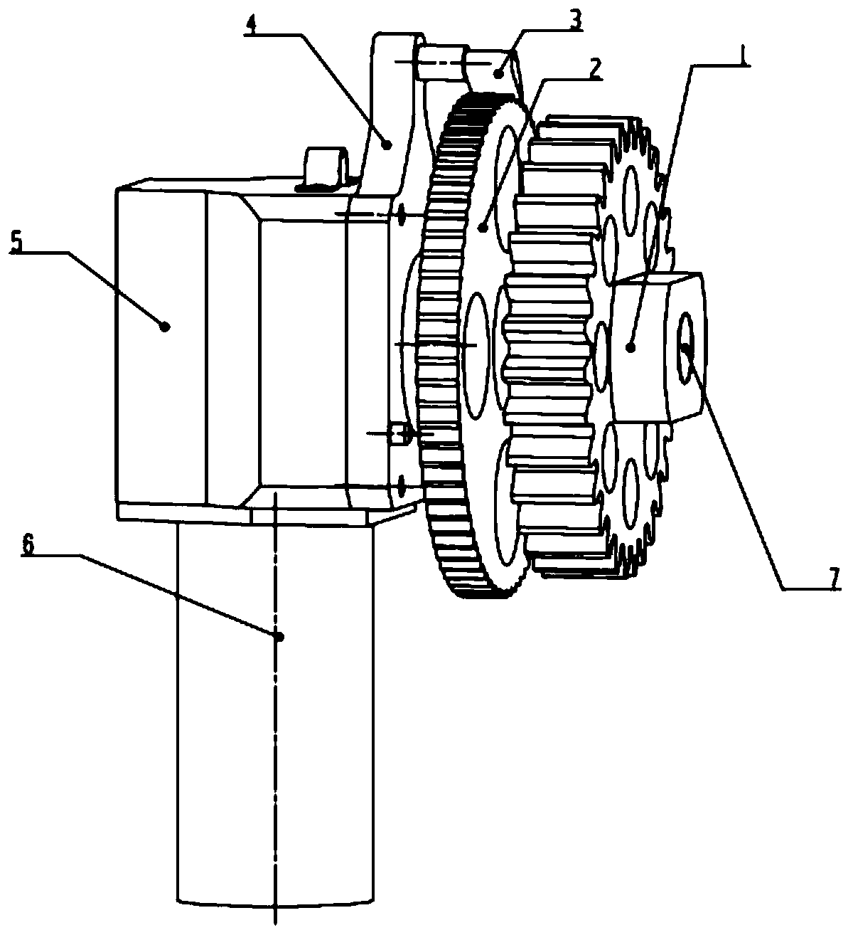
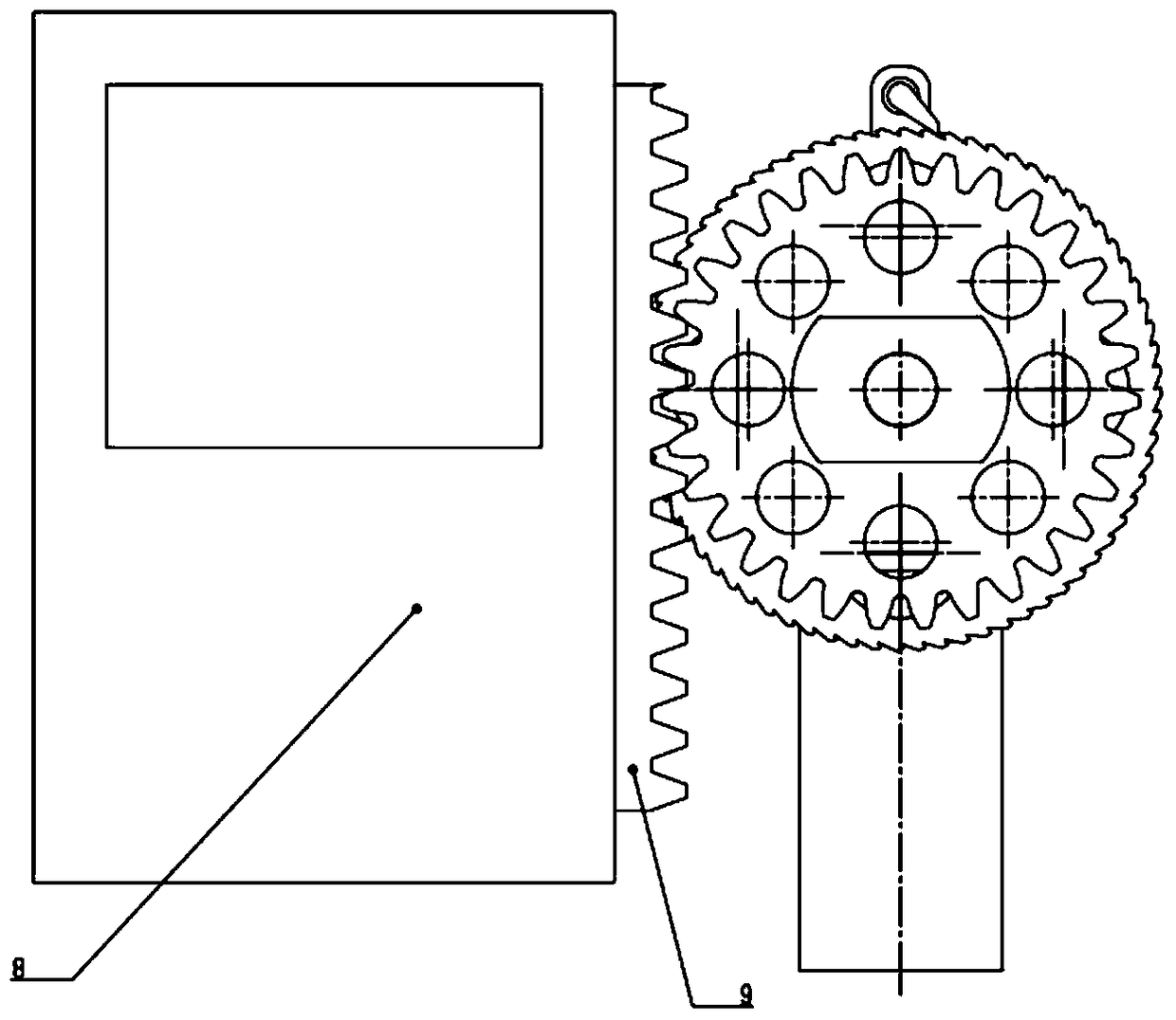
[0025] A lens propulsion actuator of the present invention consists of a transmission gear 1, a ratchet 2, a pawl 3, an installation end cover 4, a harmonic reducer housing 5, a servo motor 6, a harmonic reducer output shaft 7, a lens installation cabin 8, Gear rack 9 etc. are formed. The harmonic reducer is used as the reduction mechanism, the servo motor 6 is installed on the harmonic reducer housing 5, and the installation end cover 4 is installed on one side of the harmonic reducer housing 5, and the installation end cover 4 and the harmonic reducer housing The body 5 is fastened by screws; a protruding structure is set above the mounting end cover 4, and the pawl 3 is installed on the protruding structure; it is installed sequentially between the mounting end cover 4 and the outermost end of the output shaft 7 o...


PUM


Abstract

The invention relates to the technical field of electric servo systems, and particular to a lens pushing-in execution mechanism. The lens pushing-in execution mechanism comprises a transmission gear, a ratchet wheel, a pawl, a mounting end cover, a harmonic speed reducer housing, a servo motor, a harmonic speed reducer output shaft, a lens mounting cabin and a rack, wherein a harmonic speed reducer is adopted as a speed reducing mechanism, and the servo motor is mounted on the harmonic speed reducer housing; the ratchet wheel and the transmission gear are sequentially mounted between the mounting end cover and the outmost end of the harmonic speed reducer output shaft; and the rack is arranged on the connecting surface of the lens mounting cabin and the lens pushing-in execution mechanism, and the rack is engaged with the transmission gear. When in operation, the servo motor drives the harmonic speed reducer to do rotational motion, the harmonic speed reducer output shaft drives the ratchet wheel and the transmission gear which are fastened thereon to rotate simultaneously, the transmission gear pushes the rack, so as to push out the lens mounting cabin; and when a lens is completely pushed out, the servo motor is power off, and the pawl automatically slides toward the bottom part of a ratchet wheel tooth groove when pushing the ratchet wheel, so as to prevent the lens mounting cabin from retracting backwards.

Description

technical field [0001] The invention belongs to the technical field of electric servo systems, and in particular relates to a lens propulsion actuator. Background technique [0002] During the flight of the missile, when the target needs to be imaged, the lens device will protrude from the inside of the missile body. After the lens device is ejected, in order to prevent it from being blown back to the tail compartment by aerodynamic force, an anti-reversal function is required. When the lens device is fully extended, there are the following three options to choose from: (1) Servo the lens cabin to this position through the controller; (2) The motor of the reducer adopts a servo motor with a brake function, and by controlling the brake The lens compartment is fixed at this position; (3) a ratchet mechanism is adopted, and when the lens compartment reaches the designated position, the ratchet of the ratchet mechanism prevents the lens compartment from falling back. [0003] ...

Claims


Application Information

Patent Timeline
Patent Type & Authority Patents(China)
IPC IPC(8): H02K7/116F16D41/12
Inventor 刘源李悦伟王连丛曹东海李勇王永乐王怀王瑛琦董严熊官送翟琨房永鑫
Owner BEIJING AUTOMATION CONTROL EQUIP INST
Why Eureka
Try Eureka