Die backing plate

A backing plate and mold technology, which is applied in the field of mold backing plate, can solve the problems of inability to position the mold, inconvenient adjustment, and the lack of vibration function of the mold backing plate, and achieve the effect of uniform distribution

Inactive Publication Date: 2017-03-15
CHENGDU JUZHI IND DESIGN
View PDF3 Cites 0 Cited by
  • Summary
  • Abstract
  • Description
  • Claims
  • Application Information

AI Technical Summary

Problems solved by technology

[0005] At present, the existing mold backing plate does not have a vibration function, and the mold cannot be positioned, and the adjustment is inconvenient

Method used


Image

  • Die backing plate
  • Die backing plate

Examples


Embodiment Construction

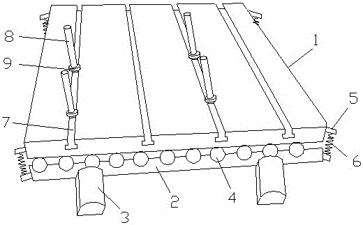
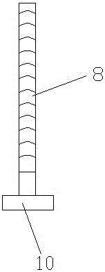
[0015] Such as figure 1 and figure 2 As shown, a mold backing plate includes a backing plate body 1, a frame 2, a vibration motor 3 and a roller 4. The backing plate body 1 is installed on the frame 2, and the two sides of the backing plate body 1 and the frame 2 are respectively There are poles 5 fixed, springs 6 are arranged between the poles 5, the poles 5 are fixedly connected with the springs 6, the vibration motor 3 is installed on the front end of the frame 2, and the roller 4 is installed in the frame 2 , the rollers 4 are provided with multiple pieces, the backing plate body 1 is provided with a groove 7, the section of the groove 7 is T-shaped, the groove 7 is equipped with a screw 8, and the screw 8 A nut 9 is mounted on it, and a baffle 10 is provided at the bottom of the screw 8 , and the baffle 10 is clamped and connected with the groove 7 .

[0016] The rollers 4 are equidistantly distributed.

[0017] The nut 9 is threadedly connected with the screw rod 8 ....


PUM


Abstract

The invention discloses a die backing plate. The die backing plate comprises a backing plate body, a framework, vibration motors and a plurality of rollers. The backing plate body is mounted on the framework; supporting rods are fixed to the two sides of the backing plate body and the two sides of the framework correspondingly; springs are disposed between the supporting rods; the supporting rods are fixedly connected with the springs; the vibration motors are mounted at the front end of the framework; the rollers are mounted inside the framework; grooves are formed in the backing plate body, and the section of each groove is in a T shape; screw rods are mounted in the grooves; screw caps are mounted on the screw rods; and baffles are arranged at the bottoms of the screw rods and connected with the grooves in a clamping mode. The die backing plate has a vibration function, can position a die and is convenient to adjust.

Description

technical field [0001] The invention relates to a mold backing plate. Background technique [0002] The mold is a tool that makes the blank into a workpiece with a specific shape and size under the action of external force. Widely used in blanking, die forging, cold heading, extrusion, powder metallurgy parts pressing, pressure casting, and compression molding or injection molding of engineering plastics, rubber, ceramics and other products. The mold has a specific contour or cavity shape, and the application of the contour shape with a cutting edge can separate the blank according to the contour line shape (punching). Applying the shape of the inner cavity can make the blank obtain the corresponding three-dimensional shape. The mold generally includes two parts, the movable mold and the fixed mold (or punch and die), which can be separated or combined. Take out the parts when they are separated, and inject the blank into the mold cavity to form when they are closed. The...

Claims


Application Information

Patent Timeline
Patent Type & Authority Applications(China)
IPC IPC(8): B29C33/00B29C33/30
CPCB29C33/00B29C33/303B29C33/308
Inventor 文国栋
Owner CHENGDU JUZHI IND DESIGN
Why Eureka
Try Eureka