Mobile phone vibrator with fastening connection and cooling function

A technology of fastening connection and vibrator, applied in the direction of electromechanical devices, electric components, telephone structure, etc., can solve the problems of complex design structure, insufficient heat dissipation of chips, high manufacturing cost, and achieve the effect of prolonging service life and good heat dissipation effect.

Active Publication Date: 2019-09-27
湖南信科诚电子有限公司
View PDF4 Cites 0 Cited by
  • Summary
  • Abstract
  • Description
  • Claims
  • Application Information

AI Technical Summary

Problems solved by technology

[0002] At present, the existing mobile phone vibrator mostly uses a motor to drive an eccentric block to rotate, and the rotating eccentric block will give the mobile phone user a vibration feeling, but the chip will generate serious heat due to insufficient heat dissipation during the long-term use of the mobile phone. The service life of the mobile phone has been reduced. In order to solve this type of problem, the mobile phone vibrator and the cooling device are combined to solve the problem in the existing technology, but the mobile phone vibrator under this technology should not only satisfy the vibration function of the mobile phone but also have the function of being a mobile phone. For the purpose of heat dissipation, two sets of structures are designed to realize these two functions in the existing technology, and at the same time rely on the positive and negative rotation of the motor to make one motor realize these two functions. The design structure in this technology is complicated, and the manufacturing The cost will also be higher, and at the same time, the long-term vibration of the mobile phone vibrator will loosen the wiring of the motor, which will increase the failure rate of the mobile phone vibrator. Therefore, it is necessary to design a mobile phone vibrator with fast connection and heat dissipation very necessary

Method used


Image

  • Mobile phone vibrator with fastening connection and cooling function
  • Mobile phone vibrator with fastening connection and cooling function
  • Mobile phone vibrator with fastening connection and cooling function

Examples


Embodiment approach

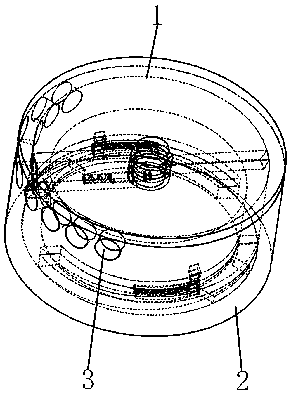
[0047] The specific implementation method is: when the vibrator mechanism 28 among the present invention does not receive the vibration signal, the motor 8 at this time will rotate at a low speed, and the first blade 12 and the second blade 14 installed on the motor 8 rotating at a low speed will It will be distributed in a state of 180 degrees, and the centrifugal column 20 will be in the first drive hole 23 and the second drive hole 24 at this time; the moving motor shaft 5 will drive the first shaft sleeve 6 installed on it to move, The moving first shaft sleeve 6 will drive the first blade 12 mounted on it to move, and at this time, one end of the centrifugal column 20 is in the first driving hole 23 and the second driving hole 24, so the moving motor shaft 5 at this time The second shaft sleeve 7 will be driven to rotate through the centrifugal column 20, and the moving second shaft sleeve 7 will drive the second blade 14 mounted on it to move. At this time, the first blad...


PUM


Abstract

The invention belongs to the mobile phone vibrator technical field, and especially relates to a tightly connected mobile phone vibrator with a heat radiation function; the mobile phone vibrator comprises a cover plate, a fixed housing, and air inlets; the fixed housing has a storage chamber; the plurality of air inlets are arranged on the inner circular surface on one side of the storage chamber;the mobile phone vibrator has a vibration function, and can diffuse heats for the mobile phone chip; a first blade and a second blade are arranged; when a motor in the mobile phone vibrator is in a low speed rotation process, the first and second blades are in a 180-degree distribution mode; the rotating first and second blades can diffuse the heat in the mobile phone, thus enabling the mobile phone chip to have a better heat radiation effect; when the motor in the mobile phone vibrator is in a high speed rotation process, the first and second blades are not in the 180-degree distribution state, thus enabling the mobile phone vibrator to have the vibration function.

Description

technical field [0001] The invention belongs to the technical field of mobile phone vibrators, in particular to a mobile phone vibrator with fastening connection and heat dissipation function. Background technique [0002] At present, the existing mobile phone vibrator mostly uses a motor to drive an eccentric block to rotate, and the rotating eccentric block will give the mobile phone user a vibration feeling, but the chip will generate serious heat due to insufficient heat dissipation during the long-term use of the mobile phone. The service life of the mobile phone has been reduced. In order to solve this type of problem, the mobile phone vibrator and the cooling device are combined to solve the problem in the existing technology, but the mobile phone vibrator under this technology should not only satisfy the vibration function of the mobile phone but also have the function of being a mobile phone. For the purpose of heat dissipation, two sets of structures are designed t...

Claims


Application Information

Patent Timeline
Patent Type & Authority Patents(China)
IPC IPC(8): H02K7/06H02K5/22H05K7/20H04M1/02
Inventor 不公告发明人
Owner 湖南信科诚电子有限公司
Why Eureka
Try Eureka