Reduction belt capable of improving the deceleration effect and reducing the vibration effect

A technology of speed bumps and speed bumps, applied in the directions of roads, road signs, traffic signals, etc., can solve the problems of trouble, waste of road convenience, etc., and achieve the effect of reducing slippage, reducing vibration effect, and increasing vibration time.

Active Publication Date: 2017-03-15
凤阳县万明电子信息科技有限公司
View PDF7 Cites 1 Cited by
  • Summary
  • Abstract
  • Description
  • Claims
  • Application Information

AI Technical Summary

Problems solved by technology

When passing through the speed bump, even if the speed slows down, the vibration frequency will not decrease significantly, and the shock absorption performance of the current car is getting better and better, causing drivers to ignore the existence of the speed bump and pass quickly, and experienced drivers even speed up. In order to reduce the vibration time of the vehicle, drivers who cannot bear the speed bumps would rather detour than pass the speed bumps. As a result, the traditional speed bumps did not bring better deceleration effects, but brought trouble and greater risks. waste of road convenience

Method used


Image

  • Reduction belt capable of improving the deceleration effect and reducing the vibration effect

Examples


Embodiment Construction

[0021] The present invention will be described in detail below in conjunction with the drawings and specific implementations:

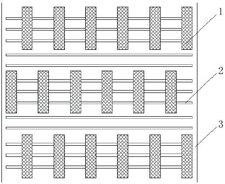
[0022] Such as figure 1 As shown, the deceleration belt of the present invention includes a longitudinal deceleration bar and a lateral anti-skid bar.

[0023] The length of the longitudinal speed bar corresponds to the length of the road. That is, the longitudinal deceleration bar is arranged longitudinally on the road surface.

[0024] The longitudinal speed bars are arranged along the width and length of the road at the same time. The longitudinal speed bumps are arranged side by side at the same interval along the width direction of the allocated road, that is, the longitudinal speed bumps are parallel to each other in the lateral direction. The longitudinal deceleration bars are arranged staggered at the same interval along the length of the allocated road, that is, the longitudinally adjacent longitudinal deceleration bars are not in the same straig...


PUM


Abstract

The invention discloses a reduction belt capable of improving the deceleration effect and reducing the vibration effect. The reduction belt includes longitudinal decelerating strips and transverse anti-slip strips. The length direction of the longitudinal deceleration strips corresponds to that of the provided roadway; meanwhile, the longitudinal decelerating strips are arranged along the width direction and the length direction of the provided road. The longitudinal decelerating strips are arranged side by side along the width direction of the provided road at the same intervals; the longitudinal decelerating strips are arranged in a staggered pattern along the length direction of the provided road at the same intervals. The longitudinal decelerating strips are arranged side by side with a width of 20-50 cm; the longitudinal decelerating strips are arranged in a staggered pattern with a width of 100-200 cm. The thickness of the transverse anti-slip strips is below that of the longitudinal decelerating strips; the length direction of the transverse anti-slip strips corresponds to the width direction of the provided road. The transverse anti-slip strips are laid at the same intervals on the road provided between the longitudinal deceleration strips.

Description

Technical field [0001] The invention relates to a traffic facility, in particular to a speed bump. Background technique [0002] In road traffic accident-prone areas, speed bumps are often laid to remind and help drivers slow down and reduce traffic accidents. Speed ​​bumps are generally plastic speed bumps or cement speed bumps, which are protruding and fixed on the road laterally. When the vehicle passes through the speed bump, the driver often slows down actively in order to avoid excessive vibration of the vehicle, so as to achieve the effect of deceleration and reduce the occurrence of traffic accidents. [0003] However, this is not the case in reality. When passing through the speed bump, even if the speed slows down, the vibration frequency will not decrease significantly, and the shock absorption performance of the current car is getting better and better. As a result, the driver often ignores the presence of the speed bump and passes quickly, and the experienced driver ...

Claims


Application Information

Patent Timeline
Patent Type & Authority Applications(China)
IPC IPC(8): E01F9/529
Inventor 李芝清
Owner 凤阳县万明电子信息科技有限公司
Why Eureka
Try Eureka