
Control method for realizing resuspension of magnetic bearings system after temporary loss of control

A magnetic levitation bearing and control method technology, applied to bearings, shafts and bearings, mechanical equipment, etc., can solve problems such as rotor or stator damage, uncontrollable levitation recovery process, etc., to improve reliability, ensure service life, and reduce damage. Effect

Active Publication Date: 2017-03-15
江苏博克斯科技股份有限公司
View PDF6 Cites 17 Cited by
  • Summary
  • Abstract
  • Description
  • Claims
  • Application Information

AI Technical Summary

Problems solved by technology

This method reduces the impact energy of the rotor by reducing the rotor speed, divides the levitation process into each degree of freedom step by step, and continuously detects that the entire recovery levitation process is uncontrollable, and it is very likely that the rotor will not be realized until the rotor speed quickly drops to zero. Resuspension, during which violent collisions between the rotor and protective bearings can cause damage to the rotor or stator

Method used


Image

  • Control method for realizing resuspension of magnetic bearings system after temporary loss of control
  • Control method for realizing resuspension of magnetic bearings system after temporary loss of control
  • Control method for realizing resuspension of magnetic bearings system after temporary loss of control

Examples


Embodiment 1

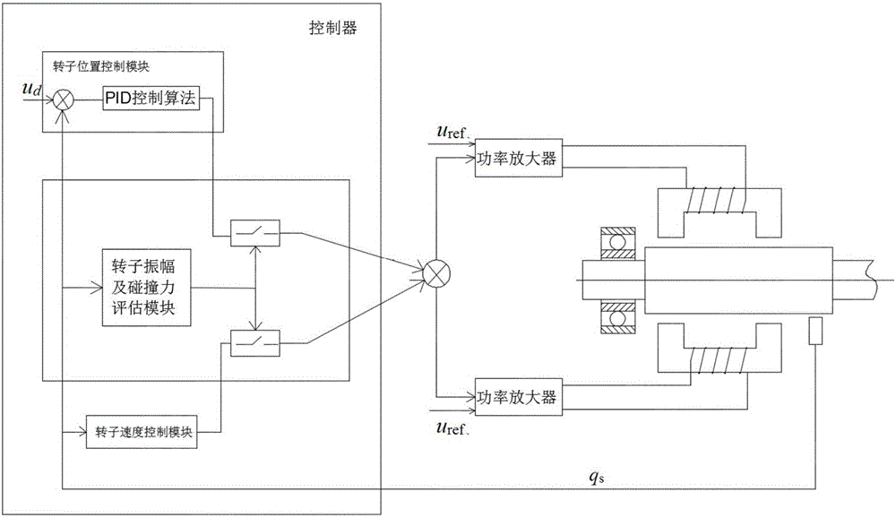
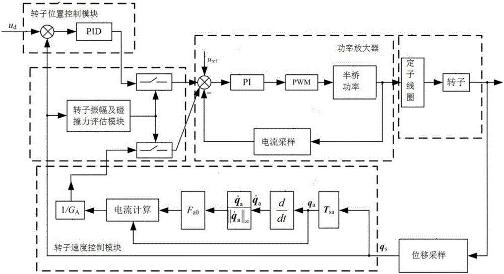
[0049] combine figure 2 with image 3 As shown, a kind of control method of the magnetic suspension bearing system in this embodiment can realize resuspension after a short period of out of control, and its steps are:

[0050] 1) Use the sensor to collect the real-time rotor vibration displacement signal q at the corresponding position of the sensor in the magnetic suspension bearing system s ;

[0051] 2) The real-time rotor vibration displacement signal q collected in step 1) s respectively input into the rotor position control module, rotor speed control module and rotor amplitude and collision force evaluation module set in the controller;

[0052] 3) The rotor amplitude and collision force evaluation module is based on the real-time rotor vibration displacement signal q collected in step 1) s Estimate the collision force value and amplitude value, and compare it with the collision force threshold and amplitude threshold value set in the rotor amplitude and collision ...


PUM


Abstract

The invention discloses a control method for realizing resuspension of a magnetic bearings system after temporary loss of control, and belongs to the field of magnetic bearings system. The control method for realizing the resuspension of the magnetic bearings system after the temporary loss of control is characterized in that a rotor position control module in a controller is used for controlling when the magnetic bearings system works normally, and a combined electromagnetic attracting force in direction opposite to the direction that the rotor deviates from a balance position can be applied to a rotor, thus ensuring that the rotor can be kept in the balance position where the suspension is to be stabilized; in case that the magnetic bearings system is subjected to temporary loss of control, a rotor speed control module in the controller is switched to control in order to apply the combined electromagnetic attracting force in the direction opposite to the rotor vibrating speed direction to the rotor, thus dissipating the rotor vibration energy caused by external distributing force, and as a result, the rotor vibrating speed can be reduced; then the rotor position control module in the controller is switched to control to enable the rotor to return to the balance position where the suspension is to be stabilized, so as to realize resuspension; the operation is convenient.

Description

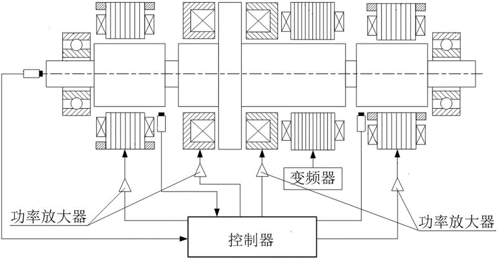
technical field [0001] The invention relates to a control method capable of realizing resuspension after a short-term loss of control of a magnetic suspension bearing system, more specifically, a control method capable of realizing re-suspension of a magnetic suspension bearing system after a short period of loss of control. Background technique [0002] Magnetic Suspension Bearing System (see figure 1 shown) generally includes: axial magnetic bearing stator, radial magnetic bearing stator, radial displacement sensor, axial displacement sensor, power amplifier, controller, rotor, motor stator, frequency converter and protective bearing. The active magnetic suspension bearing uses controllable electromagnetic force to suspend the rotor in the middle of the stator. The rotor displacement detected by the displacement sensor is compared with the displacement reference value, and then converted into a control signal by the controller, and then converted into a control signal by t...

Claims


Application Information

Patent Timeline
Patent Type & Authority Applications(China)
IPC IPC(8): F16C32/04
CPCF16C32/0442F16C32/0446F16C32/0451
Inventor 朱益利黄文生朱锡芳郑仲桥张建生
Owner 江苏博克斯科技股份有限公司
Learn More