
Flue gas waste heat recovery tower

A flue gas waste heat and recovery tower technology, applied in heat exchanger types, lighting and heating equipment, direct contact heat exchangers, etc., can solve problems such as pollution, energy loss environment, and unsatisfactory heat exchange effects

Inactive Publication Date: 2017-03-15
常州笙绿农业科技有限公司
View PDF0 Cites 0 Cited by
  • Summary
  • Abstract
  • Description
  • Claims
  • Application Information

AI Technical Summary

Problems solved by technology

[0002] High-temperature gases are often produced during industrial production. If these gases are directly discharged, they will cause energy loss and environmental pollution. Therefore, it is necessary to install a flue gas waste heat recovery tower to recover waste heat and purify the flue gas. The existing flue gas waste heat The heat exchange effect of the recovery tower is not ideal

Method used


Image

  • Flue gas waste heat recovery tower

Examples


Embodiment Construction

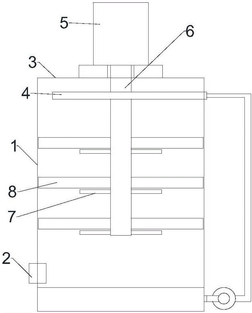
[0012] Depend on figure 1 It can be seen that the flue gas waste heat recovery tower of the present invention includes a tower body 1, an air inlet pipe 2, an air outlet 3, fillers arranged in the tower body 1, and a spray pipe 4. The upper end of the tower body 1 is provided with a lifting device 5, and the lifting device 5 is arranged on the upper end of the tower body 1. The device 5 is provided with a lifting shaft 6, and the lifting shaft 6 extends into the tower body 1. The lifting shaft 6 is provided with external threads, and the lifting shaft 6 is sleeved with a plurality of positioning discs 7 that are threadedly connected with the lifting shaft 6. The packing is composed of a plurality of packing layers 8, the packing layers 8 are supported by the positioning plate 7, and the lifting device is a lifting cylinder.

[0013] After adopting the above structure, according to the size of the air intake and the speed of gas circulation, the gap between the packing layers i...


PUM


Abstract

The invention relates to a flue gas waste heat recovery tower. The flue gas waste heat recovery tower comprises a tower body, a gas inlet pipe, a gas outlet, packing arranged inside the tower body and a spraying pipe. A lifting device is arranged at the upper end of the tower body and is provided with a lifting shaft, and the lifting shaft extends into the tower body and is provided with a plurality of locating devices. The packing is composed of a plurality of packing layers, and the packing layers are supported by the locating devices. Through the structure, according to the gas inflow amount and the gas circulation speed, the gap between the packing layers can be adjusted through the locating devices, the height of the packing can be adjusted through the lifting device and the lifting shaft, and therefore the flue gas waste heat recovery tower can adapt to flue gas of different conditions. The flue gas waste heat recovery tower is simple and reasonable in structure, convenient to operate and good in heat exchange effect and can be correspondingly adjusted according to different conditions of the flue gas.

Description

technical field [0001] The invention relates to a waste heat recovery device, in particular to a flue gas waste heat recovery tower. Background technique [0002] High-temperature gases are often produced during industrial production. If these gases are directly discharged, they will cause energy loss and environmental pollution. Therefore, it is necessary to install a flue gas waste heat recovery tower to recover waste heat and purify the flue gas. The existing flue gas waste heat The heat exchange effect of the recovery tower is not ideal. Contents of the invention [0003] The object of the present invention is to provide a flue gas waste heat recovery tower with simple and reasonable structure, convenient operation and good heat exchange effect. [0004] The technical scheme that realizes the object of the present invention is as follows: [0005] The flue gas waste heat recovery tower includes a tower body, an air inlet pipe, an air outlet, fillers arranged in the t...

Claims


Application Information

Patent Timeline
IPC IPC(8): F28C1/00F28F25/08
CPCF28C1/00F28F25/08
Inventor 应英
Owner 常州笙绿农业科技有限公司
Learn More