Matrix LED headlamp test system and matrix LED headlamp test method

A test method and technology for headlights, which are applied in diode testing, single semiconductor device testing, etc., to achieve good functions and performance, improve efficiency and accuracy, and improve safety.

Active Publication Date: 2017-03-15
H A AUTOMOTIVE SYST INC
View PDF4 Cites 2 Cited by
  • Summary
  • Abstract
  • Description
  • Claims
  • Application Information

AI Technical Summary

Problems solved by technology

Based on the above analysis, the existing test methods for LED headlamps are no longer suitable for the test requirements of matrix LED headlamps. Now there is an urgent need for a test system and method for matrix LED headlamps.

Method used


Image

  • Matrix LED headlamp test system and matrix LED headlamp test method
  • Matrix LED headlamp test system and matrix LED headlamp test method
  • Matrix LED headlamp test system and matrix LED headlamp test method

Examples


Embodiment Construction

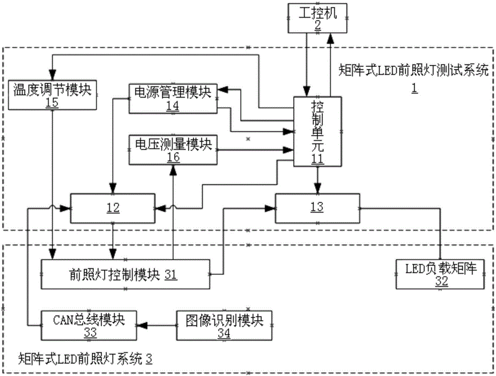
[0072] According to the attached figure 1 , 2 , give a preferred embodiment of the present invention, and give a detailed description, so that the functions and characteristics of the present invention can be better understood.

[0073] see figure 1 , a kind of matrix type LED headlamp test system 1 that the present invention implements, comprises: a control unit 11, a first fault input module 12, a second fault input module 13, a power management module 14, a temperature regulation module 15 and a voltage measurement module 16.

[0074] Wherein, the control unit 11 communicates with an external industrial computer 2, and is used to control the operation of each module in the matrix LED headlamp test system 1, collect data and perform data interaction with the industrial computer 2.

[0075] The first fault input module 12 is connected to the control unit 11 and a matrix LED headlight system 3, and is used to add an external wiring harness fault to the matrix LED headlight ...


PUM


Abstract

The invention provides a matrix LED headlamp test system and a matrix LED headlamp test method. The matrix LED headlamp test system comprises a control unit, a first fault input module, a second fault input module, and a voltage measurement module. The control unit is in communication connection with an industrial personal computer. The first fault input module is used for adding an external wiring harness fault to a matrix LED headlamp system under control of the control unit. The second fault input module is used for adding a load wiring harness fault to the matrix LED headlamp system under control of the control unit. The voltage measurement module is used for measuring voltage data of the matrix LED headlamp system and feeding the voltage data back to the control unit. According to the matrix LED headlamp test system and the matrix LED headlamp test method of the invention, a matrix LED automobile headlamp can be tested so as to improve the running reliability and safety of automobiles.

Description

technical field [0001] The invention relates to the field of vehicle testing, in particular to a matrix LED headlamp testing system and method. Background technique [0002] Although the current car headlights generally use the combination of high beam and low beam, many drivers do not consciously switch the low beam every time when the headlights are on, and if only the low beam is turned on throughout the process, it cannot achieve The driver's requirement for bad road long-distance lighting, so there is a great hidden danger to the driver's life safety. [0003] Based on the above requirements, a matrix LED car headlight has appeared in the automotive industry. There may be as many as dozens of LED light-emitting chips on one side of the high beam, instead of only one or two in the previous high beam. High brightness LED chip solution. And each LED chip of this matrix LED headlight can be individually controlled to turn on and off, and even the output brightness of each...

Claims


Application Information

Patent Timeline
Patent Type & Authority Applications(China)
IPC IPC(8): G01R31/26
CPCG01R31/2635
Inventor 宋旭波陈奇才
Owner H A AUTOMOTIVE SYST INC
Why Eureka
Try Eureka