Small high-efficiency overcurrent and overheat protector

A technology of overcurrent, overheating and protector, which is applied in the direction of thermal switch parts, etc., can solve the problems of low current induction, affecting the stability and riveting strength of the assembly riveting of the bottom plate and the shell, and the limited current range, so as to enhance the riveting strength Effect

Inactive Publication Date: 2017-03-15
YANGZHOU BAOZHU ELECTRIC APPLIANCE CO LTD
View PDF0 Cites 1 Cited by
  • Summary
  • Abstract
  • Description
  • Claims
  • Application Information

AI Technical Summary

Problems solved by technology

[0002] Similar products on the market use bimetallic overcurrent to achieve the effect of enhancing the sensitivity of current sensing. Due to the limited matching of bimetallic materials, relying on bimetal alone will inevitably lead to low current induction of the product, and the applicable current range is limited. The riveting surfaces of the bottom plate and the shell riveting lugs of similar products on the market are all flat, which will inevitably affect the stability and riveting strength of the bottom plate and shell assembly riveting

Method used


Image

  • Small high-efficiency overcurrent and overheat protector
  • Small high-efficiency overcurrent and overheat protector
  • Small high-efficiency overcurrent and overheat protector

Examples


Embodiment Construction

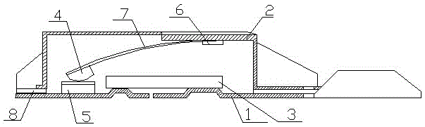
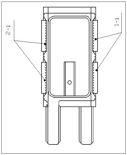
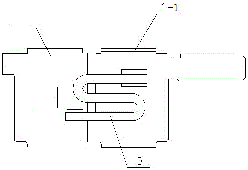
[0009] Such as figure 1 , 2 , 3, including two base plates 1, shell 2, heating wire 3, moving contact 4, static contact 5, fixed plate 6, bimetal sheet 7, insulating paper 8, and the heating wire passes between the two base plates 1 3 connection, the shell 2 is set above the two base plates 1, the static contact 5 is set above one of the base plates 1, the movable contact 4 is set on one end of the bimetal 7 and can be separated and combined above the static contact 5, The other end of the bimetal sheet 7 is connected to the inner top of the shell 2 through the fixed plate 6; the insulating paper 8 is arranged between the two bottom plates 1 and the shell 2; the edges of the two sides of the shell 2 are respectively provided with limiting grooves 2-1, Both sides of the two bottom plates 1 are provided with riveting lugs 1-1 cooperating with the limiting grooves 2-1, and the riveting lugs 1-1 are snapped into the corresponding limiting grooves 2-1 respectively.


PUM


Abstract

The invention discloses a small high-efficiency overcurrent and overheat protector, and relates to the technical field of design of overcurrent and overheat protectors for home appliance motors such as an automobile, a vacuum cleaner and a soya bean milk machine. The small high-efficiency overcurrent and overheat protector comprises two bottom boards, a shell, a heating wire, a moving contact, a static contact, a fixing board, a bimetallic strip, and an insulating paper, wherein the two bottom boards are connected through the heating wire; the shell is arranged above the two bottom boards; the static contact is arranged above one bottom board; the moving contact is arranged at one end of the bimetallic strip and is arranged above the static contact in an opening and closing mode; the other end of the bimetallic strip is connected with the inner top of the shell via the fixing board; the insulating paper is arranged between the two bottom boards and the shell; and edges at two sides of the shell are provided with limiting grooves respectively, two sides of the two bottom boards are provided with riveting lugs matched with the limiting grooves, and the riveting lugs are clamped in the corresponding limiting grooves respectively. As two sides of the shell are provided with the limiting grooves, the riveting lugs of the bottom boards are just clamped in the corresponding limiting grooves in the case of assembly, and thus, the riveting strength between the shell and the bottom boards is enhanced.

Description

technical field [0001] The invention relates to the design technical field of an overcurrent and overheat protector applied to motors of automobiles, vacuum cleaners, soybean milk makers and the like. Background technique [0002] Similar products on the market use bimetallic overcurrent to achieve the effect of enhancing the sensitivity of current sensing. Due to the limited matching of bimetallic materials, relying on bimetal alone will inevitably lead to low current induction of the product, and the applicable current range is limited. The riveting surfaces of the bottom plate and the shell riveting ear of similar products on the market are all flat, which will inevitably affect the stability and riveting strength of the assembled riveting between the bottom plate and the shell. Contents of the invention [0003] The object of the present invention is to solve the above problems and provide a small and efficient overcurrent and overheating protector that enhances curren...

Claims


Application Information

Patent Timeline
Patent Type & Authority Applications(China)
IPC IPC(8): H01H37/14H01H37/54H01H37/06
CPCH01H37/14H01H37/06H01H37/54
Inventor 杨风雷李健伟常祥卞开友范茂勇
Owner YANGZHOU BAOZHU ELECTRIC APPLIANCE CO LTD
Why Eureka
Try Eureka