Organic light-emitting device

A technology of organic light-emitting device and light-emitting structure, which is applied to electrical components, electric solid-state devices, circuits, etc., can solve problems such as temperature rise, current congestion, instability, etc., and achieve the effect of avoiding continuous temperature rise and prolonging service life.

Active Publication Date: 2017-03-15
IND TECH RES INST
View PDF7 Cites 2 Cited by
  • Summary
  • Abstract
  • Description
  • Claims
  • Application Information

AI Technical Summary

Problems solved by technology

The phenomenon of current congestion will cause the temperature of local parts to rise, and even damage the components
In addition, based on the unstable electricity caused by the manufacturing process or the material itself, short circuits may occur in some parts
Under the electrode layer where the cathodes and anodes of different polarities cover the entire surface, a local short circuit or a single-point disconnection will cause damage to the entire component

Method used


Image

  • Organic light-emitting device
  • Organic light-emitting device
  • Organic light-emitting device

Examples


Embodiment Construction

[0078] Reference will now be made in detail to the exemplary embodiments of the present invention, examples of which are illustrated in the accompanying drawings. Wherever possible, the same reference numbers will be used in the drawings and description to refer to the same or like parts.

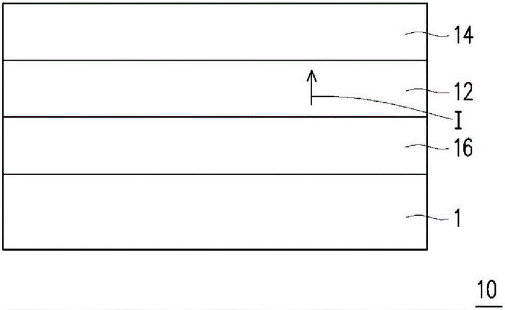
[0079] figure 1 It is a schematic cross-sectional view of an organic light-emitting device according to an embodiment. Such as figure 1 As shown, the organic light emitting device 10 includes a substrate 1 , a light emitting structure layer 12 , a first electrode layer 14 and a second electrode layer 16 . The organic light-emitting device 10 can be formed on a substrate 1, and the substrate 1 can be a circuit board, a transparent substrate, a flexible substrate or other similar plates that can carry the light-emitting structure layer 12, the first electrode layer 14 and the second electrode layer 16. shape. The light emitting structure layer 12 is sandwiched between the first electrode ...


PUM


Abstract

The invnetion provides an organic light-emitting device, which includes a first substrate, a light-emitting structure layer, a first electrode layer, a second electrode layer, a second substrate, first conduction members, a second conduction member and protection structures. The light-emitting structure layer is disposed on the first substrate. The first electrode layer is disposed on the light-emitting structure layer and includes pad-like patterns. The second electrode layer is disposed between the light-emitting structure layer and the first substrate. The second substrate is adhered on the first electrode layer and includes a first circuit and a second circuit. The first circuit includes a continuous pattern and contact portions. The first conduction members are connected between the first circuit and the first electrode layer. The second conduction member is connected between the second circuit and the second electrode layer. The protection structures respectively form open circuits or close circuits between the contact portions and the continuous pattern.

Description

technical field [0001] The invention relates to a light emitting device. Background technique [0002] With the development of optoelectronic technology, the performance and quality of organic light-emitting devices are continuously improved to be applied in various fields. For example, large-area organic light-emitting devices can be applied in light-emitting devices that provide surface light sources. Generally, an organic light-emitting device has an anode layer, a cathode layer, and a light-emitting structure layer sandwiched between the anode layer and the cathode layer. The large-area organic light-emitting device may have uneven current distribution during operation, so local parts of the large-area light-emitting device may have current congestion. The phenomenon of current congestion will cause the temperature of local parts to rise, and even damage the components. In addition, due to the unstable electricity caused by the manufacturing process or the material it...

Claims


Application Information

Patent Timeline
IPC IPC(8): H01L27/32
CPCH10K59/00H10K59/131H10K50/00H10K50/84
Inventor 颜玺轩叶文勇胡纪平钟渊山赖志明林轩宇刘玟泓陈信助
Owner IND TECH RES INST
Why Eureka
Try Eureka