Energy-saving heat-preservation water storage equipment of heating system
A heating system and equipment technology, which is applied in the field of energy-saving, thermal insulation and water storage equipment for heating systems, can solve the problems of large power consumption, low power consumption, and insufficient comfort in use, so as to save time and avoid equipment damage and danger Accidents, the effect of preventing overheating
- Summary
- Abstract
- Description
- Claims
- Application Information
AI Technical Summary
Problems solved by technology
Method used
Image
Examples
Embodiment 1
[0071] A heating system energy-saving thermal insulation water storage equipment, such asfigure 1 and figure 2 As shown, it includes a water storage tank 1, a one-way water outlet 2, a one-way water inlet 3, a U-shaped connecting plate 4, a fixing plate 5, a control assembly 6 and a heating assembly 7, and the lower right part of the water storage tank 1 is provided with a one-way water outlet 2. The lower right part of the water storage tank 1 is provided with a one-way water inlet 3, the one-way water outlet 2 is located on the left side of the one-way water inlet 3, the top of the water storage tank 1 is provided with a U-shaped connecting plate 4, and the rear part of the water storage tank 1 is provided with a fixed Plate 5, a control assembly 6 is provided between the water storage tank 1 and the U-shaped connecting plate 4, and a heating assembly 7 is provided inside the water storage tank 1.
[0072] When people need to heat, keep and store cold water, pour cold water...
Embodiment 2
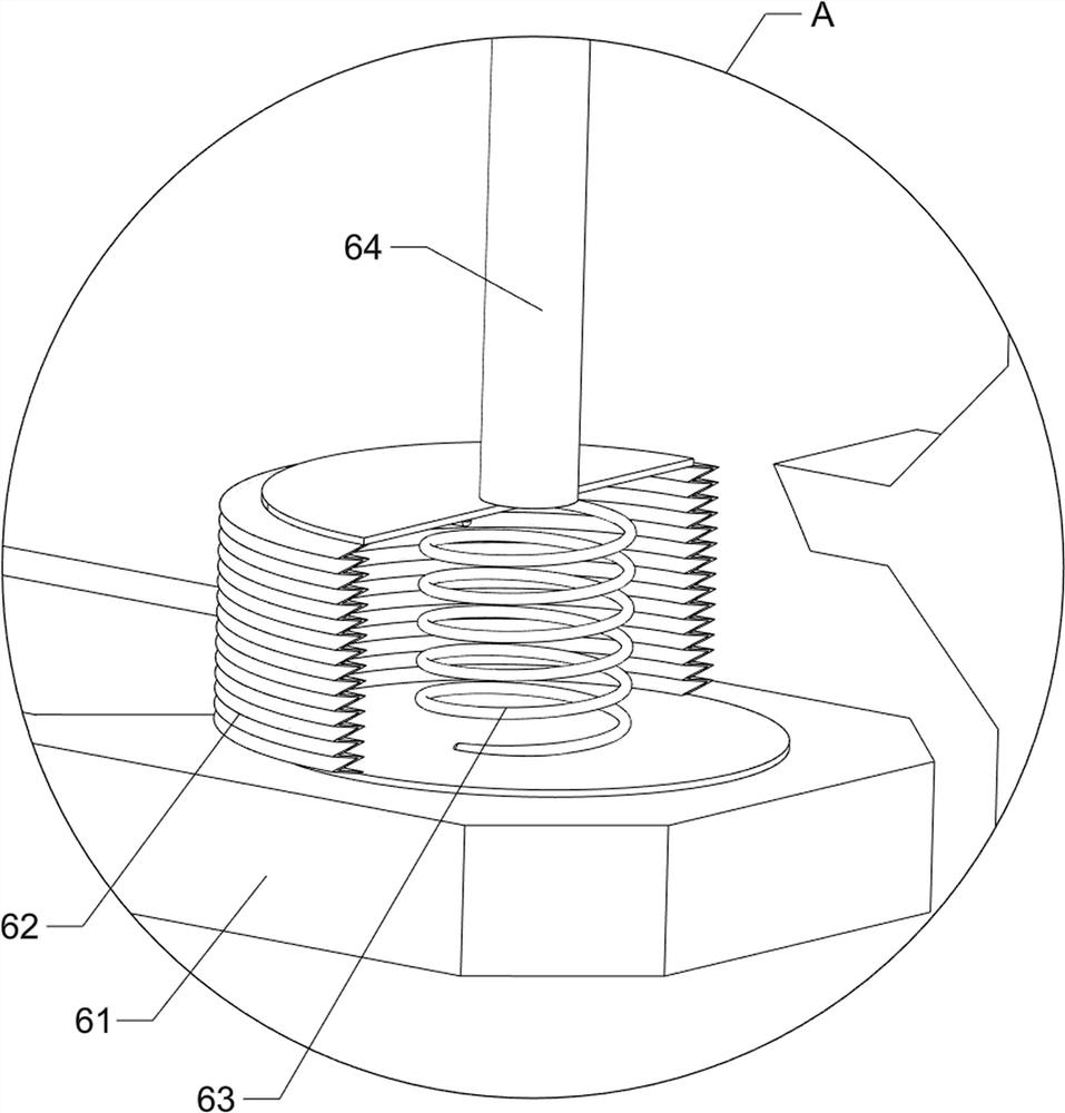
[0074] On the basis of Example 1, such as image 3 As shown, the control assembly 6 includes a support plate 61, a sealed telescopic tube 62, a first spring 63 and an L-shaped connecting rod 64, a support plate 61 is provided on the inner rear side of the water storage tank 1, and a sealed telescopic tube 62 is provided on the support plate 61. , the sealed telescopic tube 62 is provided with an L-shaped connecting rod 64, the L-shaped connecting rod 64 is slidably connected with the water storage tank 1 and the U-shaped connecting plate 4, and the sealed telescopic tube 62 is provided with a first spring 63 inside.
[0075] When people need to heat the cold water, pour cold water into the water storage tank 1 through the one-way water inlet 3, and then press down the L-shaped connecting rod 64, and the L-shaped connecting rod 64 drives the sealed telescopic tube 62 and the first spring 63 to contract Movement, when the water in the water storage tank 1 is heated, the sealed t...
Embodiment 3
[0077] On the basis of Example 2, such as Figure 4 to Figure 12 As shown, the heating assembly 7 includes a second spring 71, a start switch 72 and a heating tube 73, a start switch 72 is provided in the middle of the U-shaped connecting plate 4, and a second spring 71 is connected between the start switch 72 and the U-shaped connecting plate 4 , The right part of the U-shaped connecting plate 4 is provided with a heating pipe 73 .
[0078] People manually press the start switch 72, the start switch 72 moves downward, and the heating tube 73 starts to work to heat the cold water. At this time, the second spring 71 shrinks and moves. After the cold water is heated, the start switch 72 is manually operated to move the start switch 72 upward. Reset, the second spring 71 stretches and resets.
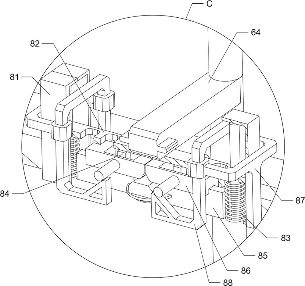
[0079] Also includes an auxiliary starting assembly 8, the auxiliary starting assembly 8 includes a first guide rail 81, a first connecting plate 82, a third spring 83, a first connecting...
PUM
 Abstract
Description
Claims
Application Information
 - R&D
- Intellectual Property
- Life Sciences
- Materials
- Tech Scout
- Unparalleled Data Quality
- Higher Quality Content
- 60% Fewer Hallucinations
Browse by: Latest US Patents, China's latest patents, Technical Efficacy Thesaurus, Application Domain, Technology Topic, Popular Technical Reports.
© 2025 PatSnap. All rights reserved.Legal|Privacy policy|Modern Slavery Act Transparency Statement|Sitemap|About US| Contact US: help@patsnap.com


