
Rotary evaporation system based on cold trap

A technology of rotary evaporation and rotary evaporator, which is applied in the field of analysis and testing, can solve problems such as low overall efficiency, damage to the life of vacuum pumps, and steam leakage, so as to improve the efficiency of liquefaction recovery, protect safety, and prevent dangerous accidents.

Pending Publication Date: 2019-03-29
北京澳维仪器有限公司
View PDF0 Cites 1 Cited by
  • Summary
  • Abstract
  • Description
  • Claims
  • Application Information

AI Technical Summary

Problems solved by technology

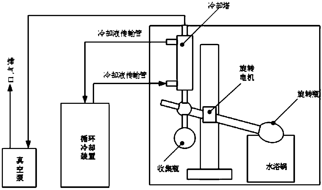
[0004] The existing rotary evaporation system has the following deficiencies: 1. The cooling liquid transmission pipeline of the circulating cooling device is too long, and the temperature loss is serious during the transmission process, which leads to low recovery efficiency of the solvent, and the unliquefied solvent vapor is discharged through the vacuum pump, which not only damages the The life of the vacuum pump, and pollute the environment
2. The single-rotary bottle rotary evaporator can only process one sample at a time during use, which cannot meet the needs of users for batch sample processing; although the multi-rotary bottle rotary evaporator is connected in parallel with multiple rotary bottles, due to sequential heating and evaporation, the overall efficiency It is still not high, and during the working process, because the evaporation speed of the samples in each rotary bottle cannot be completely synchronized, some samples have been evaporated to dryness, and some samples have not been evaporated to dryness. Spinner bottle, it will destroy the working state of other spinner bottles
3. During the use of the rotary evaporation system, if an unexpected power failure occurs, the vacuum pump and circulating cooling water will stop working, but the water in the heating pot is still at a high temperature, and the samples in the rotary bottle are still being heated continuously. Air pressure will gradually increase, prone to dangerous accidents
During the working process, if the user forgets to start the vacuum pump after starting the rotating motor due to the negligence of the user, the steam pressure will be too high and dangerous accidents will easily occur; if the circulation cooling device is forgotten to be turned on, the steam cannot be effectively condensed and recovered. A large amount of steam leaks out, causing serious air pollution in the laboratory and endangering the health of users

Method used


Image

  • Rotary evaporation system based on cold trap
  • Rotary evaporation system based on cold trap
  • Rotary evaporation system based on cold trap

Examples


Embodiment 1

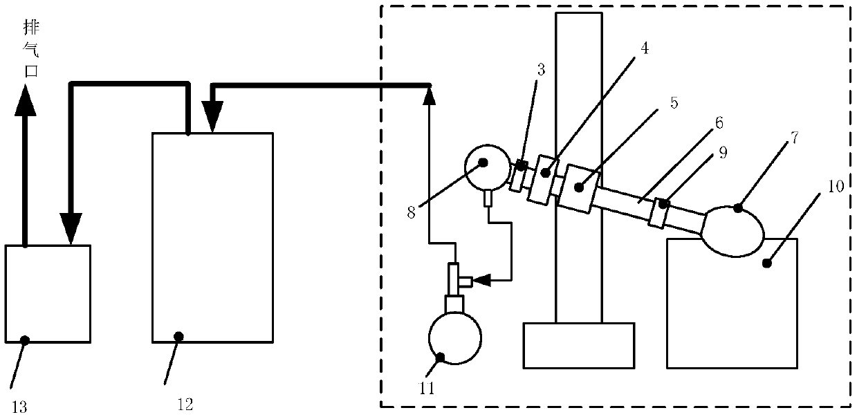
[0027] Embodiment 1: see attached figure 2 , a cold trap-based rotary evaporation system, which includes: a rotary evaporator vacuum pump 13 and a cold trap 12;

[0028] The rotary evaporator includes: a heating device 10, a rotating motor 5, a rotating bottle 7, a buffer bottle 11 and a hollow bottle 8; the output of the rotating motor 5 is connected to the rotating hollow shaft 6; one end of the rotating hollow shaft 6 is connected to the rotating bottle through the second interface 9 7. The other end of the rotating hollow shaft 6 is inserted into the sealing interface 4; the sealing interface 4 is connected to one interface of the hollow bottle 8 through the first interface 3; the second interface of the hollow bottle 8 is connected to the mouth of the buffer bottle 11 through the pipeline The other interface of the tee at the mouth of the buffer bottle 11 is connected to the gas inlet of the cold trap 12 through the pipeline, and the gas outlet of the cold trap 12 is con...

Embodiment 2

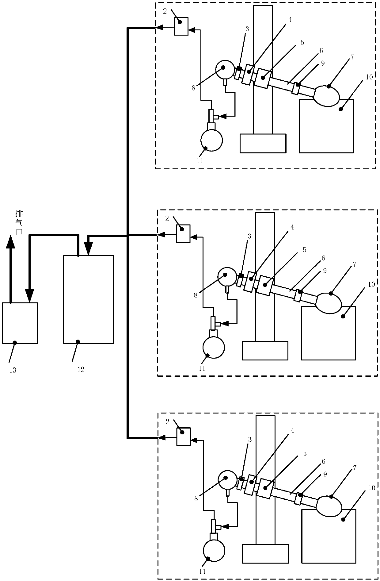
[0031] Embodiment 2: see attached image 3 , in order to realize the demand of batch processing sample, on the basis of embodiment 1, the quantity of rotary evaporator is set to more than two, arranges in array form; A switching solenoid valve 2 is arranged on the pipeline.

[0032] This solution realizes the use of multiple rotary evaporators in parallel under the condition of configuring a vacuum pump 13 and a cold trap 12, and arbitrarily terminates the work of one or more rotary evaporators, without affecting the normal operation of other rotary evaporators; Each rotary evaporator can be kept working independently by controlling the on-off of the switch solenoid valve 2 on the pipeline connecting each rotary evaporator with the cold trap 12 . When a certain rotary evaporator completes the work, the switch solenoid valve 2 of the rotary evaporator is placed in a closed state, and the switch valve is placed in a conduction state, so that the air pressure in the rotary bottl...

Embodiment 3

[0033] Embodiment 3: see attached Figure 4 , on the basis of Embodiment 1 or 2, the on-off valve and the heating device 10 are specifically defined:

[0034] The switch valve can use vacuum release solenoid valve 1 or manual rotary valve 14 or can also be as Figure 4 As shown, two kinds of valves are set at the same time; the vacuum release solenoid valve 1 is set on the pipeline between the buffer bottle 11 and the switch solenoid valve 2, and the manual rotary valve 14 is directly set at the third interface of the hollow bottle 8; Valve 1 or manual rotary valve 14 all allow the air pressure in rotary bottle 7 to be in a normal atmospheric pressure state;

[0035] The heating device 10 includes: a hot liquid tank 10.1, a water pump 10.2 and a water bath 10.3; the rotary bottle 7 is placed in the hot liquid tank 10.1; the water bath 10.3 sends hot water to the bottom of the hot liquid tank 10.1 through the water pump 10.2; the hot liquid tank 10.1 is set There is an overfl...


PUM


Abstract

The invention belongs to the technical field of analytical tests, and particularly relates to a rotary evaporation system. The rotary evaporation system based on the cold trap comprises a rotary evaporator, a vacuum pump and the cold trap; the rotary evaporator comprises a heating device, a rotary motor, a rotary bottle, a buffer bottle and a hollow bottle; the output end of the rotary motor is connected to a rotary hollow shaft; one end of the rotary hollow shaft is connected to the rotary bottle through a second connector; the other end of the rotary hollow shaft is inserted into a sealing connector; the hollow bottle is connected to the sealing connector, the buffer bottle and a gas inlet of the cold trap; a gas outlet of the cold trap is connected to a gas inlet of the vacuum pump; a gas outlet of the vacuum pump is communicated with the atmosphere; the rotary bottle is arranged in the heating device; and a switch valve communicated with the atmosphere is further arranged at the position of the hollow bottle. According to the system, the cold trap is adopted to replace a cooling circulation device, solvent steam is introduced into the cold trap and then is liquefied and collected, a cooling tower and cooling fluid are not required to be transmitted, and therefore the liquefaction recovery efficiency of the solvent steam is improved.

Description

technical field [0001] The invention belongs to the technical field of analysis and testing, in particular to a rotary evaporation system. Background technique [0002] Rotary evaporation system laboratory common equipment, such as attached figure 1 As shown, the rotary evaporation system consists of a rotary evaporator, a heating pot, a cooling tower, a circulating cooling device, a vacuum pump, etc., wherein the number of rotary bottles on the rotary evaporator can be one or more; the rotary evaporator is mainly used for Continuous distillation of volatile solvents under reduced pressure is used in chemistry, chemical engineering, biomedicine and other fields. [0003] When the rotary evaporation system is working, first put the sample to be processed into the rotary bottle, start the vacuum pump, and circulate the cooling device. Start the rotating motor to make the rotating bottle rotate at a constant speed at the most suitable speed to increase the evaporation area. ...

Claims


Application Information

Patent Timeline
Patent Type & Authority Applications(China)
IPC IPC(8): B01D3/08B01D8/00
CPCB01D3/085B01D8/00
Inventor 孙金龙彭红顺陈立萍孙宏伟
Owner 北京澳维仪器有限公司
Learn More