Magnetic electrode button

An electrode and magnetic technology, applied in the direction of circuits, conductive connections, electrical components, etc., can solve the problems of inconvenient application, high cost, complex button battery structure and preparation process, etc., and achieve the effect of convenient portability, simple structure, and reduced volume

Active Publication Date: 2017-03-15
SHENZHEN POMAGTOR PRECISION ELECTRONICS CO LTD
View PDF8 Cites 17 Cited by
  • Summary
  • Abstract
  • Description
  • Claims
  • Application Information

AI Technical Summary

Problems solved by technology

[0002] Nowadays, with the development of science and technology and the fast pace of people's life, the requirements for charging technology are also increasing. The charging of many electronic housings, especially wearable housings, needs to be realized in a more convenient and fast way. Therefore, button batteries have emerged as the times require. The structure and preparation process of the current button battery are complicated, the cost is high, a special carrier is required, and the application is inconvenient. Therefore, it is necessary to develop a button battery for fast charging that is easy to manufacture and install, easy to carry and apply

Method used


Image

  • Magnetic electrode button
  • Magnetic electrode button
  • Magnetic electrode button

Examples


Embodiment Construction

[0025] The present invention will be described in further detail below in conjunction with the accompanying drawings.

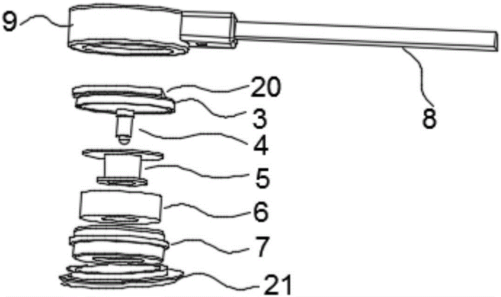
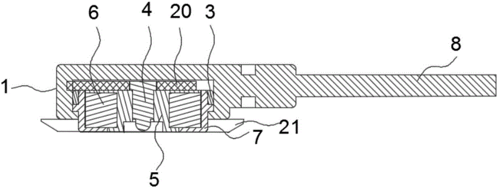
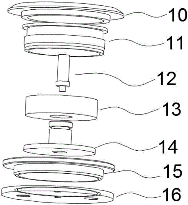
[0026] Figure 1-Figure 8 A magnetic electrode button according to an embodiment of the present invention is schematically shown. As shown in the figure, the magnetic electrode button includes a magnetic electrode button male seat 1 and a magnetic electrode button female seat 2. Both the magnetic electrode button male seat 1 and the magnetic electrode button female seat 2 contain magnets, and the magnetic electrode button male seat 1 and the magnetic electrode button female seat 2 are connected together by magnets and form a conduction, and the conductive ends of the magnetic electrode button male seat 1 and the magnetic electrode button female seat 2 are all connected through magnet adsorption.

[0027] Both the magnetic electrode button male seat 1 and the magnetic electrode button female seat 2 include a positive conductor, a negative conductor, a magnet,...


PUM


Abstract

The invention discloses a magnetic electrode button, which comprises a magnetic electrode button male seat and a magnetic electrode button female seat, wherein the magnetic electrode button male seat and the magnetic electrode button female seat comprise magnets; the magnetic electrode button male seat and the magnetic electrode button female seat are connected together through attraction of the magnets and are conducted; and conducting ends of the magnetic electrode button male seat and the magnetic electrode button female seat are butted and conducted through adsorption of the magnets. The magnetic electrode button is fixed on a carrier to serve as a button in use; the magnetic electrode button female seat or the magnetic electrode button male seat is fixed by forming an opening in the carrier; and the magnetic electrode button is connected with the magnetic electrode button male seat and the magnetic electrode button female seat in use for charging and data transmission. The magnetic electrode button disclosed by the invention comprises the magnets, a positive conducting body and a negative conducting body, so that connection and conduction of the magnetic electrode button male seat and the magnetic electrode button female seat are achieved to form the magnetic electrode button; and the magnetic electrode button is simple in structure, easy to install and convenient to carry, is arranged on clothes or a wearable shell and is used for other charging fields.

Description

technical field [0001] The invention relates to the technical field of charging, in particular to a magnetic electrode button. Background technique [0002] Nowadays, with the development of science and technology and the fast pace of people's life, the requirements for charging technology are also increasing. The charging of many electronic casings, especially wearable casings, needs to be realized in a more convenient and fast way. Therefore, button batteries have emerged as the times require. The structure and preparation process of the current button battery are complicated, the cost is high, a special carrier is required, and the application is inconvenient. Therefore, it is necessary to develop a button battery for fast charging that is easy to manufacture and install, easy to carry and apply. Contents of the invention [0003] In order to solve the above-mentioned problems in the prior art, according to one aspect of the present invention, a magnetic electrode butto...

Claims


Application Information

Patent Timeline
Patent Type & Authority Applications(China)
IPC IPC(8): H01R13/62H01R11/30
CPCH01R11/30H01R13/6205H01R24/38A41D1/005A41D13/0051A41D2400/12H05B1/0272H05B2203/036H05K1/0212H05K1/181
Inventor 魏正鹏
Owner SHENZHEN POMAGTOR PRECISION ELECTRONICS CO LTD
Why Eureka
Try Eureka