
Circuit for automatic time-delay conduction after switch tripping

A technology of switching after tripping, applied in the direction of automatic disconnection of emergency protection devices, circuit devices, emergency protection circuit devices, etc., can solve the problems of manual closing, trouble in production and life, etc. effect of use

Active Publication Date: 2017-03-15
CHONGQING YUZHAN ELECTRICAL CO LTD
View PDF5 Cites 0 Cited by
  • Summary
  • Abstract
  • Description
  • Claims
  • Application Information

AI Technical Summary

Problems solved by technology

[0002] A number of circuit breakers with short-circuit protection function are usually installed in the low-voltage power distribution box or low-voltage power distribution cabinet. When the circuit breaker trips automatically, people can generally quickly judge whether it is affected by the excessive power of the back-end load, and take corresponding measures. Power consumption adjustment measures, such as disconnecting the power connection of high-power load equipment or closing other unimportant load connections, and re-closing the tripped switch after a certain time interval, the current circuit breaker only has an independent switch function, It usually requires personnel to re-close the trip switch at the distribution box. In the actual production and living environment, it is not always possible to manually close the switch in time, which will bring unnecessary troubles to people's production and life. Therefore, it is necessary to design A new circuit solves

Method used


Image

  • Circuit for automatic time-delay conduction after switch tripping
  • Circuit for automatic time-delay conduction after switch tripping

Examples


Embodiment Construction

[0017] The technical solutions in the present invention will be further described below in conjunction with the accompanying drawings and embodiments.

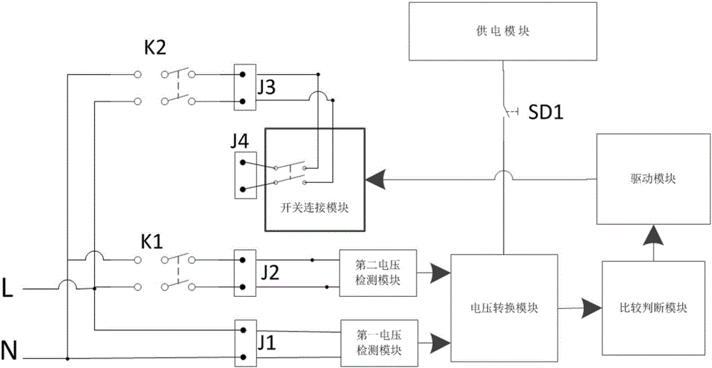
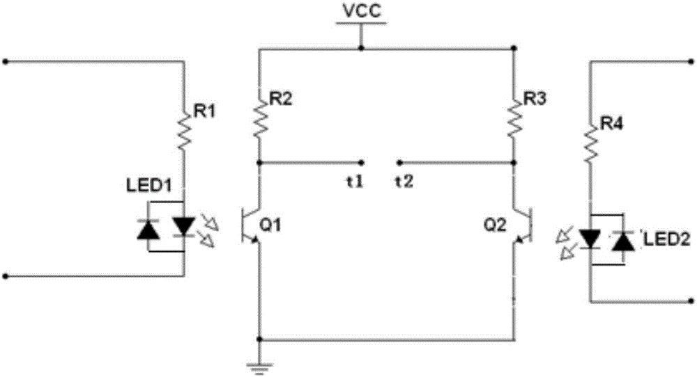
[0018] It is used for automatic time-delayed turn-on circuit after the switch trips, such as figure 1 As shown, it includes the first input terminal J1, the second input terminal J2, the third input terminal J3 and the transfer output terminal J4 which are independent of each other, and also includes the first voltage detection module, the second voltage detection module, the voltage conversion module, the comparison Judgment module, drive module, manual switch SD1, switch connection module, power supply module and standby switch K2; the first input terminal J1 is used to be connected in parallel with the input terminal of the monitored switch K1 and the input terminal of the standby switch K2, and the second The input terminal J2 is used to connect in parallel with the output terminal of the monitored switch K1, the third inp...


PUM


Abstract

The invention provides a circuit for automatic time-delay conduction after switch tripping. The circuit is composed of a first input terminal, a second input terminal, a third input terminal, a change-over output terminal, a first voltage detection module, a second voltage detection module, a voltage conversion module, a comparison determination module, a driving module, a switch connection module, a power supply module and a standby switch, wherein the first input terminal, the second input terminal, the third input terminal, and the output terminal are independent to each other. The change-over output terminal serving as a standby switch output terminal connected to the third input terminal is connected with a rear-end load. The first voltage detection module is connected with the first input terminal electrically; the second voltage detection module is connected with the second input terminal electrically; the outputs of the first voltage detection module and the second voltage detection module are connected with the voltage conversion module; and the input of the comparison determination module is connected with the output terminal of the voltage conversion module. The circuit has the following beneficial effect: automatic time-delay conduction after once tripping can be provided for a monitoring switch.

Description

technical field [0001] The invention relates to the field of power electronics, in particular to a circuit for automatically delaying conduction after a switch trips. Background technique [0002] A number of circuit breakers with short-circuit protection function are usually installed in the low-voltage power distribution box or low-voltage power distribution cabinet. When the circuit breaker trips automatically, people can generally quickly judge whether it is affected by the excessive power of the back-end load, and take corresponding measures. Power consumption adjustment measures, such as disconnecting the power connection of high-power load equipment or closing other unimportant load connections, and re-closing the tripped switch after a certain time interval, the current circuit breaker only has an independent switch function, It usually requires personnel to re-close the trip switch at the distribution box. In the actual production and living environment, it is not a...

Claims


Application Information

Patent Timeline
Patent Type & Authority Applications(China)
IPC IPC(8): H02H3/06H02H7/22
CPCH02H3/06H02H7/22
Inventor 刘国胜孙大年
Owner CHONGQING YUZHAN ELECTRICAL CO LTD
Learn More