

UAV minimum speed automatic protection control system
A protection control, drone technology, applied in the control/regulation system, speed/acceleration control, non-electric variable control and other directions, can solve the problem that the drone does not have the minimum flight speed, and achieve the effect of low false alarm rate
Active Publication Date: 2011-04-27
CHENGDU AIRCRAFT INDUSTRY GROUP
View PDF0 Cites 1 Cited by
- Summary
- Abstract
- Description
- Claims
- Application Information
AI Technical Summary
Problems solved by technology
The object of the present invention is not to possess minimum flight speed control and relevant failure place for prior art unmanned plane
Method used
View moreImage
Smart ImageViewing Examples

Examples
Embodiment Construction
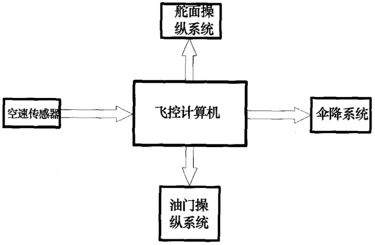
[0030] Rudder surface control system: according to the command that the control computer sends, the steering surface is deflected to a specified angle.
[0033] The systems are usually transmitted by digital signals.
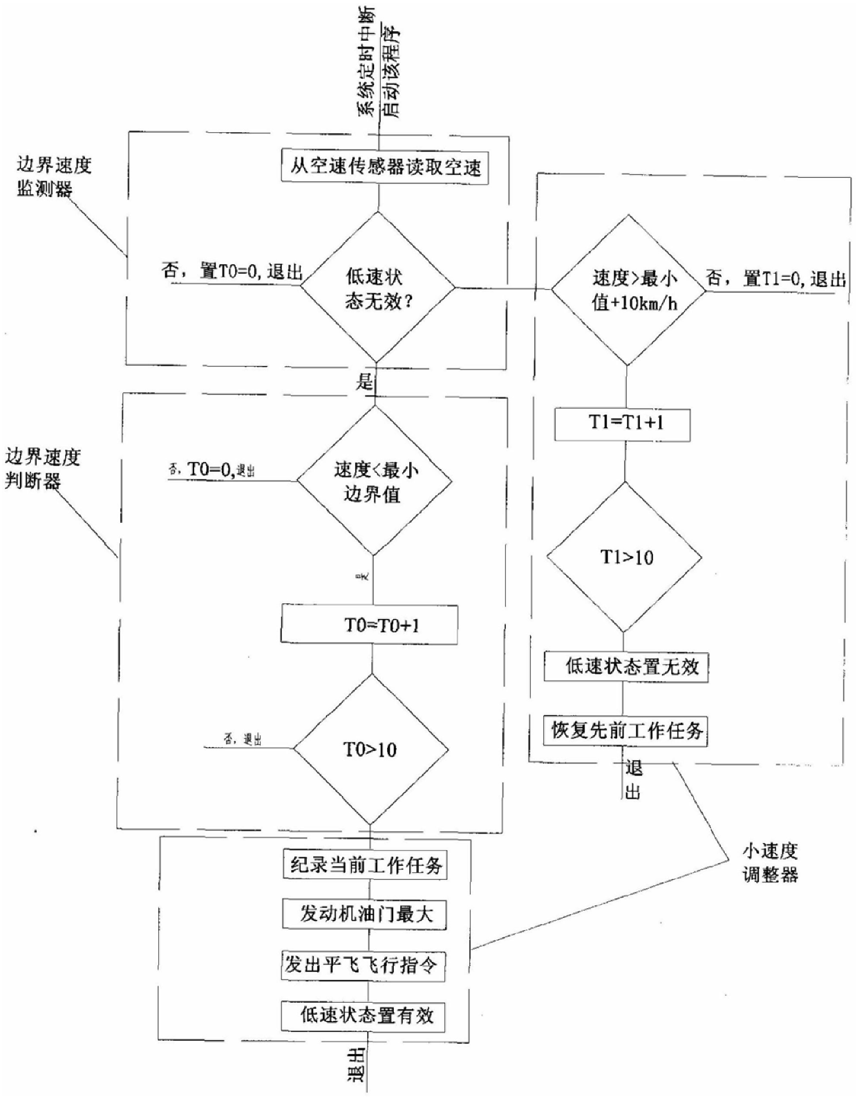
[0052] e) Exit the program.
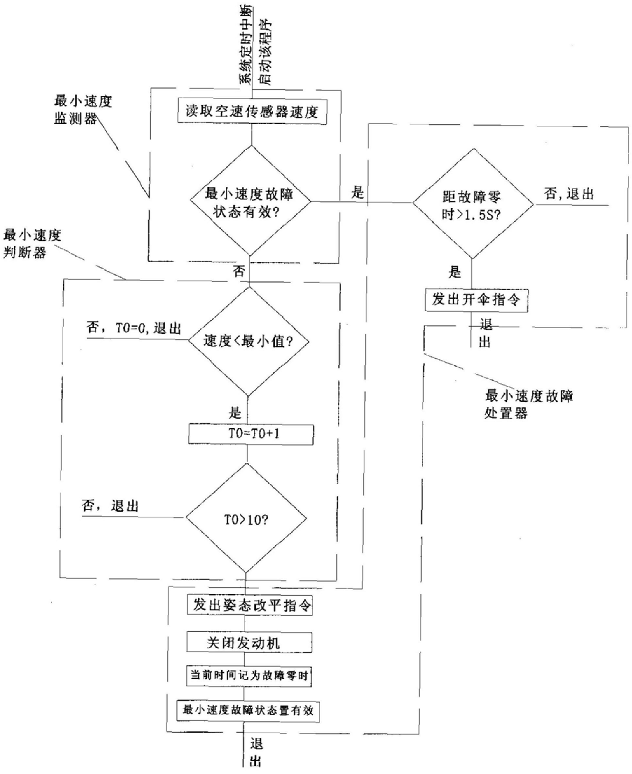
[0061] b) shut down the engine;
[0064] e) Exit the program.
Login to View More PUM
 Abstract
The invention relates to a minimum speed protection control system for unmanned aerial vehicles, comprising: a control computer as a control center and an airspeed sensor electrically connected to it, the computer is equipped with two minimum speed fault handling modules that are started by timing interruption, and the two The modules include: a minimum speed over-boundary control module and a minimum speed fault handling control module, wherein the minimum speed over-boundary control module is used to monitor the aircraft speed obtained by the airspeed sensor system in real time, and control the speed of the aircraft within the allowable range; the minimum speed The fault handling control module is triggered by a clock timing interrupt, and its minimum fault handler controls the parachute recovery of the aircraft. According to the current flight speed obtained by the airspeed sensor, when the speed is lower than the minimum speed limit, the invention can adjust the throttle opening of the engine to resume normal flight, and can control the parachute recovery of the aircraft when the minimum speed cannot be controlled, which solves the problem Some UAVs do not have the minimum flight speed control and are prone to stall and cause flight accidents.
Description
UAV minimum speed automatic protection control system technical field [0001] The present invention relates to an automatic protection and control system for flying speed of unmanned aerial vehicles. Background technique In the prior art, the unmanned aircraft carrying out the air-to-air combat mission beyond visual range is different from manned aircraft The disadvantage is that the UAV is small in size, the onboard system is complex, the loading space, the capacity of the control computer, and the calculation speed are limited. The control system is simple, and the sensors carried by itself are few. Prior art unmanned aerial vehicles are due to the limitation of cost, aircraft loading space and load. system, it is impossible to fully install high-precision sensors. The flight control ability is weak, the autonomous control ability is poor, and the failure itself It cannot be ruled out that crash accidents are prone to occur. It requires the ground control center to...
Claims
Login to View More Application Information
Patent Timeline
 IPC IPC(8): G05D13/00B64C19/02
Inventor李涛宋承志夏斌
OwnerCHENGDU AIRCRAFT INDUSTRY GROUP