
Constant-temperature constant-pressure adjustable cupping cup

A constant temperature and constant pressure, adjustable technology, applied in the field of cupping, can solve problems such as the cupping tank body does not have a ventilation function, the air is turbid, and the treatment effect is reduced

Pending Publication Date: 2017-03-22
GUANGZHOU INFUMEDI MEDICAL TECH CO LTD
View PDF6 Cites 4 Cited by
  • Summary
  • Abstract
  • Description
  • Claims
  • Application Information

AI Technical Summary

Problems solved by technology

[0004] (2) The pressure in the cupping tank is not constant. After the vacuum pump pumps the tank to a certain pressure, the vacuum pump is not running. Since the opening of the tank and the skin cannot be completely sealed, the pressure in the tank will gradually decrease. , thereby reducing the therapeutic effect;
[0005] (3) The cupping tank does not have the function of ventilation. During the cupping treatment, the air in the tank will not circulate. As time goes by, the air in the tank will become turbid, which will be harmful to the skin where the cupping is performed. influences

Method used


Image

  • Constant-temperature constant-pressure adjustable cupping cup
  • Constant-temperature constant-pressure adjustable cupping cup
  • Constant-temperature constant-pressure adjustable cupping cup

Examples


Embodiment Construction

[0024] In order to make the object, technical solution and advantages of the present invention clearer, the present invention will be further described in detail below in conjunction with the accompanying drawings and embodiments. It should be understood that the specific embodiments described here are only used to explain the present invention, not to limit the present invention.

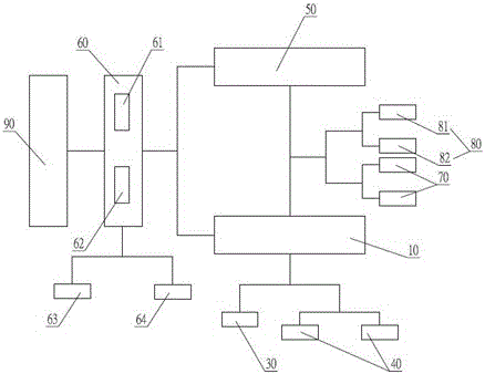
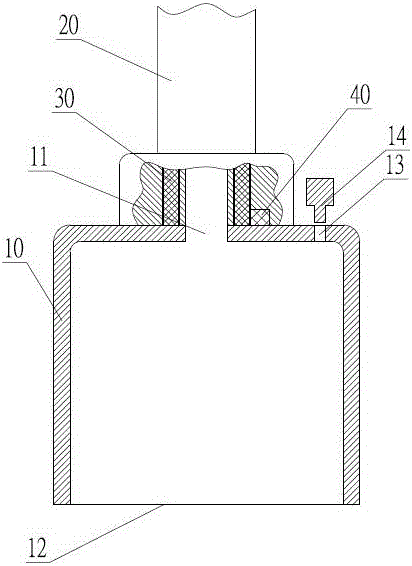
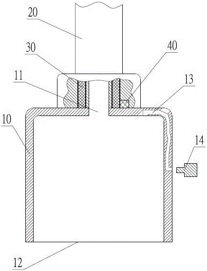
[0025] Such as figure 1 As shown, a constant temperature and constant pressure adjustable cupping in this embodiment at least includes a tank body 10, a vacuum pump 50 and a main control unit 60, wherein the main control unit 60 is a PLC or a single chip microcomputer in the prior art. Such as figure 2 , image 3 As shown, one end of the tank body 10 is an opening 12 , and the end away from the opening 12 is a suction port 11 , and the suction port 11 is connected to a vacuum pump 50 through a pipeline 20 .

[0026] In order to keep the pressure inside the tank 10 constant, a solenoid valve 80 ...


PUM


Abstract

The invention discloses a constant-temperature constant-pressure adjustable cupping cup, which at least comprises a cup body, a vacuum pump and a main control unit. A heating device and temperature sensors are arranged on the cup body, and the heating device and the temperature sensors are connected with the main control unit, so that the goals of controlling the temperature in the cup body in real time and maintaining the temperature in the cup body in the constant-temperature state can be achieved; a throttle valve, a pressure relief valve and pressure sensors are arranged on a pipeline formed between the cup body and the vacuum pump, and the vacuum pump, the throttle valve, the pressure relief valve and the pressure sensors are connected with the main control unit, so that the goals of controlling the pressure in the cup body in real time and maintaining the pressure in the cup body in the constant pressure state can be achieved; an air exchange passage communicating with the outside is arranged on the cup body, so that external fresh air can be supplemented into the cup body at any time in the cupping process; and the air flow speed of the air exchange passage is smaller than the air suction speed of the vacuum pump, so that the inside of the cup body is enabled to be maintained in the relatively stable negative pressure state under the continuous work state of the vacuum pump.

Description

technical field [0001] The invention relates to cupping, in particular to an adjustable constant temperature and pressure cupping. Background technique [0002] The electric cupping that is commonly used at present sucks out the air in the tank body by a vacuum pump, so that negative pressure is generated in the tank body, and then the skin is sucked. But present electric cupping has the following weak points: [0003] (1) The cupping tank does not have a heating function. If the tank can be heated and kept at a constant temperature, the therapeutic effect will be better; [0004] (2) The pressure in the cupping tank is not constant. After the vacuum pump pumps the tank to a certain pressure, the vacuum pump is not running. Since the opening of the tank and the skin cannot be completely sealed, the pressure in the tank will gradually decrease. , thereby reducing the therapeutic effect; [0005] (3) The cupping tank does not have the function of ventilation. During the cup...

Claims


Application Information

Patent Timeline
Patent Type & Authority Applications(China)
IPC IPC(8): A61M1/08A61H9/00A61F7/00
CPCA61M1/0003A61M1/08A61F7/007A61H9/0057A61F2007/0095A61H2201/0207A61M2205/36A61M2205/3368A61M2205/33A61M2205/18
Inventor 窦文安姚拥军方国成陈胜华陈灿婵
Owner GUANGZHOU INFUMEDI MEDICAL TECH CO LTD
Learn More