
Cushion with switchable bearing parts and switching control method
A cushion and position technology, applied in the field of cushion and transformation control, can solve the problems of high price, uneven temperature control, large volume, etc.
- Summary
- Abstract
- Description
- Claims
- Application Information
AI Technical Summary
Problems solved by technology
Method used
Image

Examples
Embodiment 1
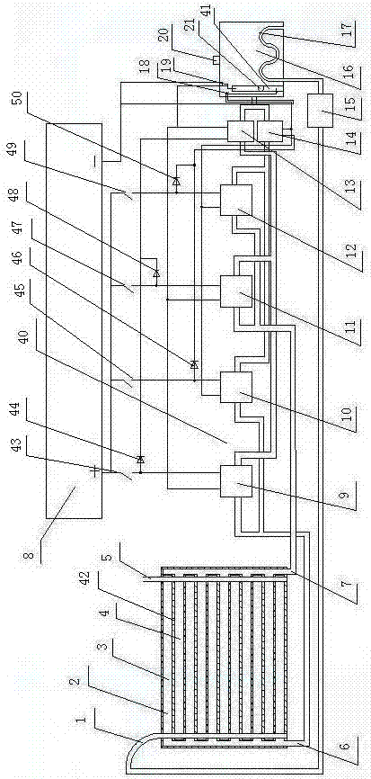
[0037] A cushion with a convertible load-bearing part, which consists of: a cushion 42, the cushion is connected to the control device 40 through a pipeline, the control device is connected to the medium tank 16 through a pipeline, and the cushion includes a bottom plate 2 , the bottom plate has inlet and outlet pipe A, part number: 6, inlet and outlet pipe B, part number: 7, the inlet and outlet pipe A and a group of grooves A, part number: 3 upper coating or groove lining The capsule forms a connected cavity, the inlet and outlet tube B and a group of grooves B, part number: 4 The upper covering film or the groove lining capsule forms a connected cavity, and the soft film on the groove is respectively connected to the grooves The ends of the groove A and the groove B are fixedly connected.
Embodiment 2
[0039] According to the seat cushion with convertible load-bearing parts described in Embodiment 1, the groove A and the groove B are arranged adjacent to each other, and the two ends of the soft film are respectively equipped with air inlet pipes 1, 1 and 2 respectively. Outlet pipe 5, the groove A and groove B are strip-shaped or circular or square-shaped, the medium box includes a lower limit switch 18 and an upper limit switch 19, and a cylinder is installed in the medium box 41. The lower end of the cylinder has a round hole, a floating ball 21 is placed in the cylinder, a temperature controller 20 is installed on the medium box, and a heat dissipation pipe 17 is installed in the medium box. One end of the heat dissipation pipe is connected to the air inlet pipe 1 through a high-pressure blower 15 , and the other end of the heat dissipation pipe is connected to the air conditioner through a temperature controller 20 through a pipeline.
Embodiment 3
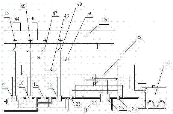
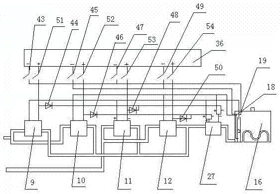
[0041] like figure 1 As shown, according to the seat cushion with convertible load-bearing parts according to claim 1, the control device is two single-phase pumps in a forward and reverse complementary manner, which includes a controller A, part number: 8, and the controller Normally open switch A of A, part number: 43, normally open switch B, part number: 45, normally open switch C, part number: 47, normally open switch D, part number: 49, one end is connected to the positive end of the power supply, and the other One end is respectively connected to the positive ends of solenoid valve A, part number: 9, solenoid valve B, part number: 10, solenoid valve C, part number: 11, and solenoid valve D, part number: 12, and the control device It also includes a reverse pump 13 and a forward pump 14. The control device also includes a medium tank, which is provided with an upper limit switch 19 and a lower limit switch 18. The positive terminal on the solenoid valve A and the positive...
PUM
 Abstract
Description
Claims
Application Information