Cutting blade and cutting tool

A technology of cutting inserts and cutting tools, applied in cutting inserts, tools for lathes, turning equipment, etc., can solve the problems of increased deformation of fasteners, vibration of cutting inserts, chipping, etc., to achieve vibration attenuation, light cutting , the effect of suppressing collapse

Active Publication Date: 2017-03-22
ZHUZHOU CEMENTED CARBIDE CUTTING TOOLS CO LTD
View PDF5 Cites 3 Cited by
  • Summary
  • Abstract
  • Description
  • Claims
  • Application Information

AI Technical Summary

Problems solved by technology

Although this structure solves the impact of positioning on the performance of the cutting blade to a certain extent, when the cutting blade bears a large load, the deformation of the fastener increases, and the side of the blade rotates upwards and tilts relative to the sipe, resulting in the side of the cutting blade The positioning surface and the cutter body are separated, and the clamping force is completely provided by the fastener, resulting in severe vibration or even collapse of the cutting insert

Method used


Image

  • Cutting blade and cutting tool
  • Cutting blade and cutting tool
  • Cutting blade and cutting tool

Examples


Embodiment 1

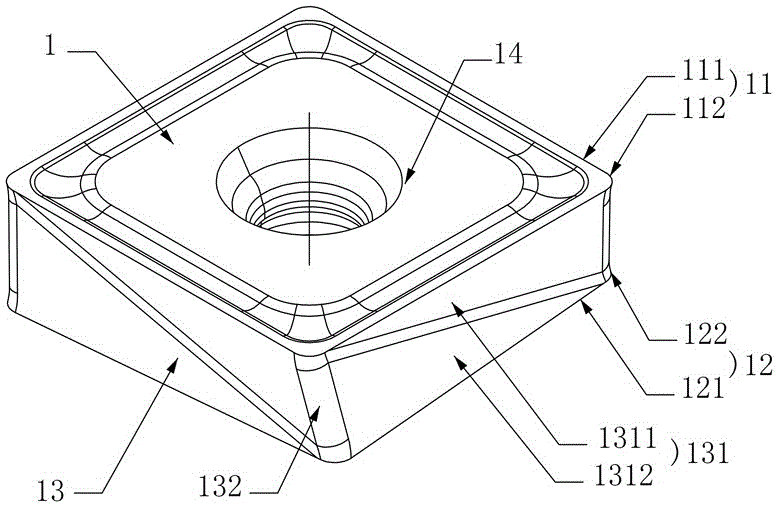
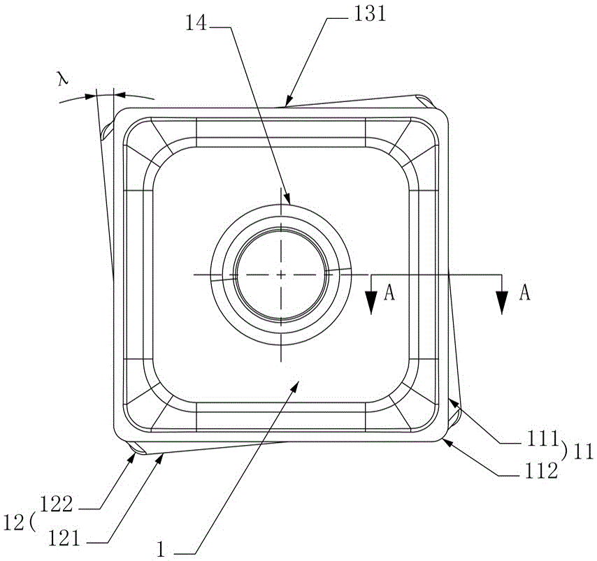
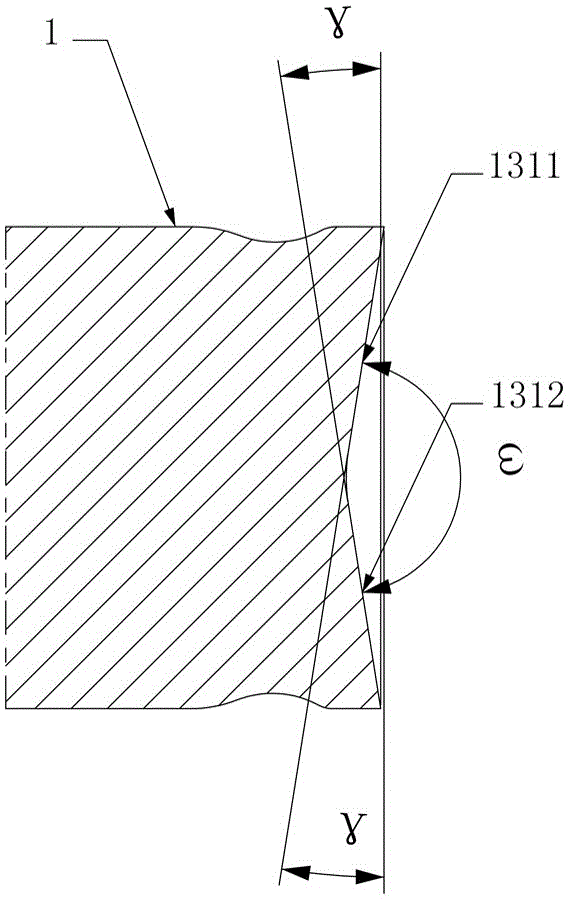
[0040] Figure 1 to Figure 3The first embodiment of the cutting insert of the present invention is shown, the cutting insert comprises a insert body 1, the insert body 1 comprises an upper cutting portion 11 and a lower cutting portion 12, the upper cutting portion 11 is composed of a plurality of upper main cutting edges 111 and upper Turning cutting edges 112 are connected in sequence, and the lower cutting portion 12 is composed of a plurality of lower main cutting edges 121 and lower turning cutting edges 122 connected in sequence. The upper main cutting edge 111 and the lower main cutting edge 121 have the same positive acute angle cutting relief angle, At least a part of the upper main cutting edge 111 on the same side protrudes from the lower main cutting edge 121 on the same side, and at least a part of the lower main cutting edge 121 on the same side protrudes from the upper main cutting edge 111 on the same side. In this structure, the upper cutting part 11 is compos...

Embodiment 2

[0046] Such as Figure 4 and Figure 5 As shown, the second embodiment of the cutting insert of the present invention, the cutting insert is basically the same as that of Embodiment 1, the only difference is that in this embodiment, the upper side 1311 and the lower side 1312 are at the diagonal positions of the main side 131 The upper turning cutting edge 112 on the right intersects the lower turning cutting edge 122 on the left. In this structure, because in the same main side surface 131, the upper main cutting edge 111 or the lower main cutting edge 121 participating in the side cutting in the upper cutting unit or the lower cutting unit participating in the cutting and the corresponding lower main cutting edge 121 or upper The main cutting edge 111 interacts with each other, the upper main cutting edge 111 or the lower main cutting edge 121 of the face cutting cannot participate in the cutting with a complete positive relief angle, and the upper cutting unit or the lower...

Embodiment 3

[0048] Such as Figure 6 and Figure 7 As shown, the third embodiment of the cutting blade of the present invention, the cutting blade is basically the same as Embodiment 1, the only difference is that eight upper cutting units with the same cutting shape are arranged on the upper surface, and eight upper cutting units with the same cutting shape are arranged on the lower surface. Eight lower cutting units with the same cutting shape, so that the cutting blade can be used 16 times, which has a better cost performance advantage. The rest of the parts that are not discussed are completely the same as the first embodiment of the disclosed cutting insert of the present invention, and will not be repeated here.


PUM


Abstract

The invention discloses a cutting blade. Upper main cutting edges and lower main cutting edges have the same positive acute-angled cutting clearance angles; at least parts of the upper main cutting edges on the same side are projected relative to the lower main cutting edges on the same side; and at least parts of the lower main cutting edges on the same side are projected relative to the upper main cutting edges on the same side. A cutting tool comprises a cutter body, a fastening piece and the cutting blade; at least one cutter groove is formed in the cutter body; at least two groups of chip holding grooves are formed in each cutter groove; a blade body is fixed in the cutter grooves through the fastening piece; the cutter grooves include cutter groove side surfaces and cutter groove bottom surfaces; the upper surface or the lower surface of the blade body is tightly bonded with the cutter groove bottom surfaces; and the upper side surface or the lower side surface of the blade body is tightly bonded with the cutter groove side surfaces. The cutting blade has the advantages of low cutting vibration, light and fast cutting, good cost performance, good positioning rigidity, good chip removing performance, long service life and capability of being widely applied to rough machining and finish machining.

Description

technical field [0001] The invention mainly relates to the field of cutting processing, in particular to a cutting blade and a cutting tool. Background technique [0002] The bottom surface and side surface of the cutting insert with double-sided groove structure generally adopt the vertical plane contact method for positioning. This kind of cutting blade is easy to manufacture and easy to process; the side positioning surface of the cutting blade has high precision and large contact area, so this type of cutting blade has excellent impact resistance and high dimensional accuracy; at the same time, the large positioning contact area can make cutting When the insert bears a large load, only a small deformation occurs on the positioning surface, which effectively ensures the consistency of the dimensional accuracy of the cutting tool in the static state and during processing, and improves the tool stability of the cutting tool under different working conditions. At the same t...

Claims


Application Information

Patent Timeline
Patent Type & Authority Applications(China)
IPC IPC(8): B23B27/00
CPCB23B27/00B23B2200/286
Inventor 江爱胜王社权刘敏易为倪兰项兴东
Owner ZHUZHOU CEMENTED CARBIDE CUTTING TOOLS CO LTD
Why Eureka
Try Eureka