
A synchronous feeding manipulator for machine tools

A technology of manipulator and machine tool, applied in the field of synchronous refueling manipulator for machine tools, can solve the problems of prolonging single-piece processing cycle, increasing refueling time, reducing processing efficiency, etc., to speed up processing cycle, increase refueling time, and reduce refueling effect of time

Inactive Publication Date: 2018-11-16
XIAN AERONAUTICAL POLYTECHNIC INST
View PDF6 Cites 0 Cited by
  • Summary
  • Abstract
  • Description
  • Claims
  • Application Information

AI Technical Summary

Problems solved by technology

The stop and start of the machine tool spindle will increase the refueling time, prolong the single-piece processing cycle, and reduce the processing efficiency, so this problem needs to be solved

Method used


Image

  • A synchronous feeding manipulator for machine tools
  • A synchronous feeding manipulator for machine tools
  • A synchronous feeding manipulator for machine tools

Examples


Embodiment Construction

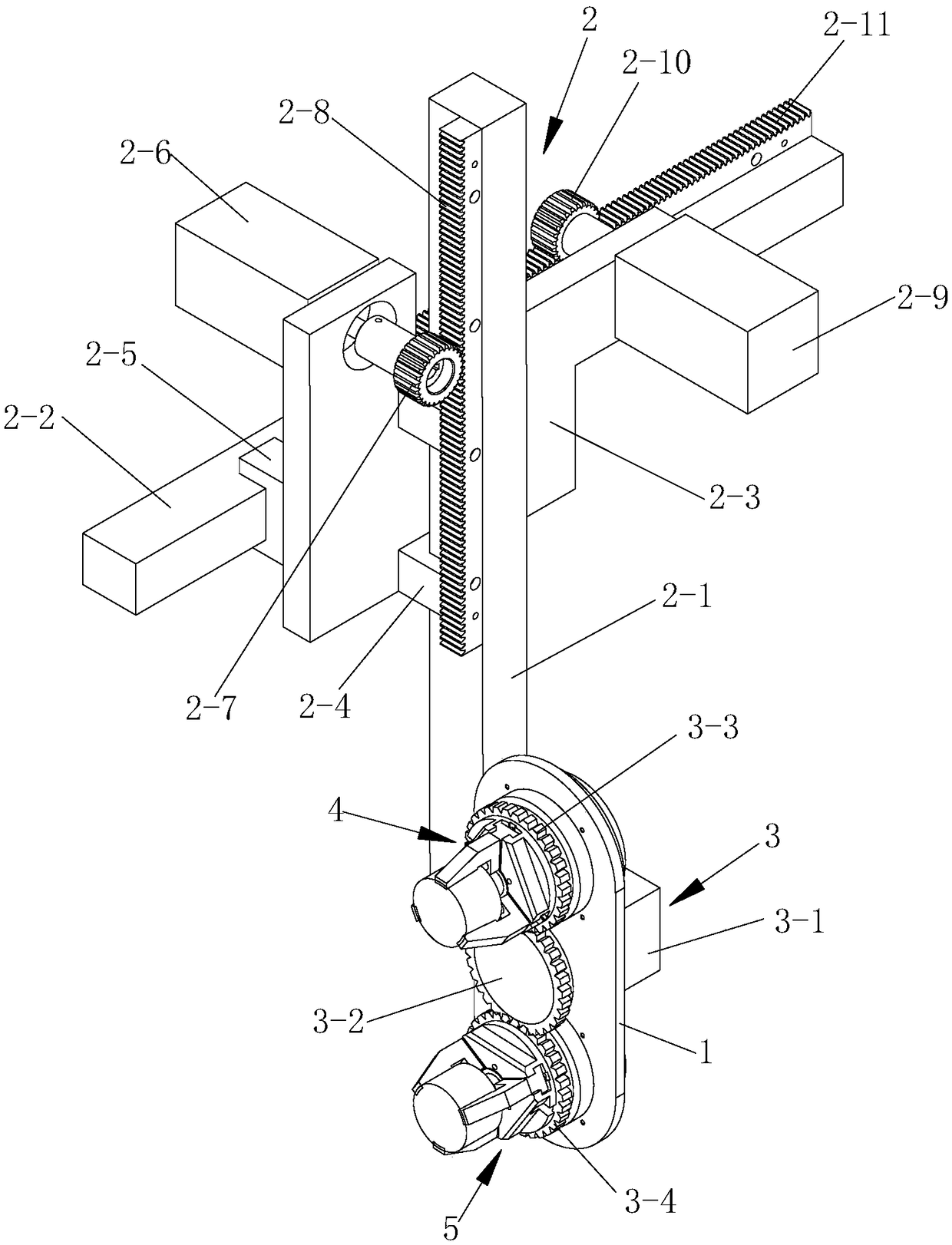
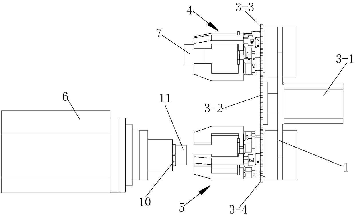
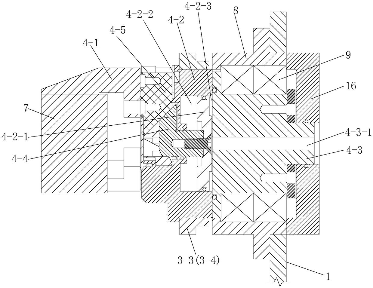
[0064] Such as figure 1 , figure 2 and image 3 A synchronous refueling manipulator for a machine tool is shown, including a jaw fixing plate 1, and a moving mechanism 2 for driving the jaw fixing plate 1 to move up and down and left and right; the jaw fixing plate 1 is provided with a useful It is used to install the blank 7 on the machine tool chuck 10, the blank 7 is used to unload the workpiece 11 processed from the blank 7 from the machine tool chuck 10, and it is used to drive the upper jaw 5. The power device 3 for synchronously rotating the material claw 4 and the blanking claw 5 with the machine tool spindle 6; the loading claw 4 and the blanking claw 5 both include a plurality of claw fingers 4-1 and are used to drive a plurality of the claws The drive means for the fingers 4-1 to move away from each other or to approach each other simultaneously.

[0065] In this embodiment, when the synchronous refueling manipulator for the machine tool is in use, that is, afte...


PUM


Abstract

The invention discloses a synchronous material change mechanical hand for a machine tool. The synchronous material change mechanical hand comprises a material paw fixed plate, and a moving mechanism used for driving the material paw fixed plate to move up and down and move left and right, wherein a feeding paw used for mounting a blank on a machine tool chuck, a discharge paw used for discharging a workpiece processed through the blank from the machine tool chuck, and a power device used for driving the feeding paw and the discharge paw to synchronously rotate along with a machine tool spindle; and the feeding paw and the discharge paw comprise a plurality of material paw fingers and driving devices used for driving the plurality of material paw fingers to be away from each other at the same time or to be close to each other at the same time. According to the synchronous material change mechanical hand for the machine tool, feeding and discharge actions can be carried out during the high-speed operation process of the machine tool spindle, so that the material change time is effectively shortened, and the processing efficiency of the workpiece is improved.

Description

technical field [0001] The invention belongs to the technical field of machine tool refueling, and in particular relates to a synchronous refueling manipulator for machine tools. Background technique [0002] With the increasing demand for less-manned and unmanned processing, various manipulators are more and more used in the processing field to grasp parts according to a fixed program. At present, when the manipulator claws widely used in the market are changing the material at the main shaft end, it is necessary to stop the main shaft from rotating, and then the manipulator claws complete the unloading and loading actions. Then the machine tool spindle starts to rotate to process the next workpiece. The stop and start of the machine tool spindle will increase the refueling time, prolong the single-piece processing cycle, and reduce the processing efficiency, so this problem needs to be solved. Contents of the invention [0003] The object of the present invention is to...

Claims


Application Information

Patent Timeline
Patent Type & Authority Patents(China)
IPC IPC(8): B23Q7/04
CPCB23Q7/04
Inventor 武欣竹韩斌慧宋育红杨继盛
Owner XIAN AERONAUTICAL POLYTECHNIC INST
Learn More