T-shaped ring edge belt sander

An abrasive belt machine and abrasive belt technology are applied in the direction of abrasive belt grinders, grinding workpiece supports, grinding machines, etc., which can solve the problems of complex installation and debugging, high labor intensity, and large space occupation, and achieve improved accuracy, high degree of automation, and The effect of increasing the service life

Active Publication Date: 2017-03-22
TIANJIN TTX GROUP
View PDF9 Cites 5 Cited by
  • Summary
  • Abstract
  • Description
  • Claims
  • Application Information

AI Technical Summary

Problems solved by technology

[0002] At present, the existing tableware facade grinding generally adopts manual operation. The general process is that the worker holds the tableware and aligns its facade with the abrasive belt grinder for grinding. During the grinding process, the material should be moved according to the shape of the tableware. In order to achieve the purpose of full overall grinding, this method has the following disadvantages: low processing efficiency, poor precision, high labor cost, high labor intensity, and accidents; very few manufacturers also have some automatic grinding equipment, but these equipment exist The following disadvantages: complex structure, large space occupation, complicated installation and debugging, and high energy consumption; so how to design a grinding equipment for tableware processing that can overcome the shortcomings of the above two situations at the same time has become a research topic for those skilled in the art

Method used


Image

  • T-shaped ring edge belt sander
  • T-shaped ring edge belt sander
  • T-shaped ring edge belt sander

Examples


Embodiment Construction

[0021] It should be noted that, in the case of no conflict, the embodiments of the present invention and the features in the embodiments can be combined with each other.

[0022] In describing the present invention, it should be understood that the terms "center", "longitudinal", "transverse", "upper", "lower", "front", "rear", "left", "right", " The orientations or positional relationships indicated by "vertical", "horizontal", "top", "bottom", "inner" and "outer" are based on the orientations or positional relationships shown in the drawings, and are only for the convenience of describing the present invention and Simplified descriptions, rather than indicating or implying that the device or element referred to must have a particular orientation, be constructed and operate in a particular orientation, and thus should not be construed as limiting the invention. In addition, the terms "first", "second", etc. are used for descriptive purposes only, and should not be understood ...


PUM


Abstract

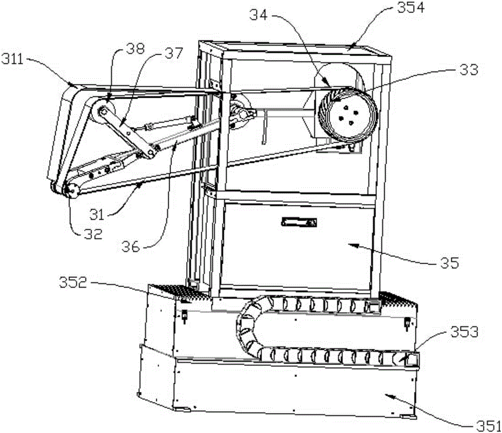
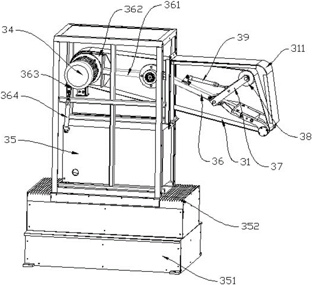
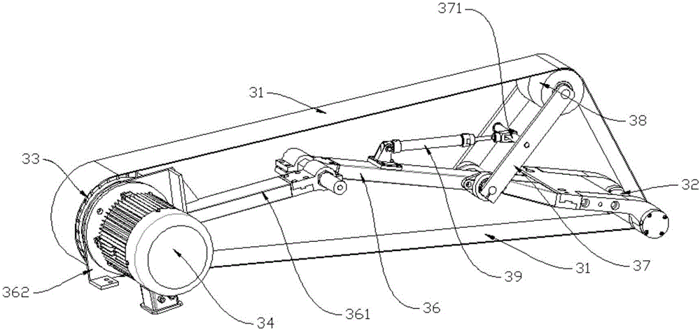
The invention provides a T-shaped ring edge belt sander and belongs to the field of tableware processing equipment. The T-shaped ring edge belt sander comprises a sanding belt, a shell, a grinding wheel, a driving wheel and a driving motor, wherein the grinding wheel, the driving wheel and the driving motor are fixed to the shell. The sanding belt sequentially winds around the outer ring of the grinding wheel and the outer ring of the driving wheel, the driving motor drives the driving wheel to rotate, and the shell can move forwards and backwards in the transmission direction of the sanding belt. The grinding wheel is fixed to the shell through a grinding arm, the grinding arm is arranged on the inner ring of the sanding belt, locking arms are hinged to the two sides of the grinding arm, the ends, away from the grinding arm, of the locking arms are rotationally connected with an adjusting wheel, the adjusting wheel is tangent to the sanding belt, a connection rod is arranged in the middles of the locking arms located on the two sides of the grinding arm, the end, away from the sanding belt, of the grinding arm is provided with an adjusting air cylinder, and a force output shaft of the adjusting air cylinder is fixedly connected with the middle of the connection rod. The T-shaped ring edge belt sander is simple in structure, convenient to adjust and debug, automatic in production and high in efficiency.

Description

technical field [0001] The invention belongs to the field of tableware processing equipment, in particular to a T-shaped ring edge abrasive belt machine. Background technique [0002] At present, the existing tableware facade grinding generally adopts manual operation. The general process is that the worker holds the tableware and aligns its facade with the abrasive belt grinder for grinding. During the grinding process, the material should be moved according to the shape of the tableware. In order to achieve the purpose of full overall grinding, this method has the following disadvantages: low processing efficiency, poor precision, high labor cost, high labor intensity, and accidents; very few manufacturers also have some automatic grinding equipment, but these equipment exist The disadvantages are as follows: complex structure, large space occupation, complicated installation and debugging, and high energy consumption; so how to design a tableware processing grinding equip...

Claims


Application Information

Patent Timeline
Patent Type & Authority Applications(China)
IPC IPC(8): B24B21/16B24B21/18B24B21/20B24B55/04B24B41/06B24B55/00
CPCB24B21/16B24B21/18B24B21/20B24B41/06B24B55/00B24B55/04
Inventor 田捷才
Owner TIANJIN TTX GROUP
Why Eureka
Try Eureka