High-efficient dewatering dyeing machine

A water-dyeing, high-efficiency technology, applied in the direction of liquid/gas/steam removal, liquid/gas/steam removal by scraping, vibration treatment, etc., can solve problems such as easy to stain clothes, low work efficiency, and affect the quality of cloth. Achieve the effects of improving diffusion efficiency, maintaining the surrounding environment, and reducing the handling weight

Inactive Publication Date: 2017-03-22
ZHENGZHOU TIANSHUN ELECTRONICS TECH CO LTD
View PDF4 Cites 7 Cited by
  • Summary
  • Abstract
  • Description
  • Claims
  • Application Information

AI Technical Summary

Problems solved by technology

[0002] In the process of dyeing cloth, the traditional method is to manually put the cloth into the dye vat, and then manually drag the other end of the cloth slowly for dip-dyeing. People directly contact with the dye, which is easy to stain the clothes. The dye contains many harmful substances. , it is easy to damage the health of workers, and the manual operation cannot evenly control the time of dyeing. Due to the inconsistent speed of different workers, the quality of the dyed cloth is not the same, and the dyeing is uneven, which affects the quality of the whole batch of cloth; Take it out of the dyeing vat, you need to wring out the dyeing water on the fabric manually, the work efficiency is low, and it will affect the health of the workers

Method used


Image

  • High-efficient dewatering dyeing machine
  • High-efficient dewatering dyeing machine

Examples


Embodiment Construction

[0014] The following will clearly and completely describe the technical solutions in the embodiments of the present invention with reference to the accompanying drawings in the embodiments of the present invention. Obviously, the described embodiments are only some, not all, embodiments of the present invention. Based on the embodiments of the present invention, all other embodiments obtained by persons of ordinary skill in the art without making creative efforts belong to the protection scope of the present invention.

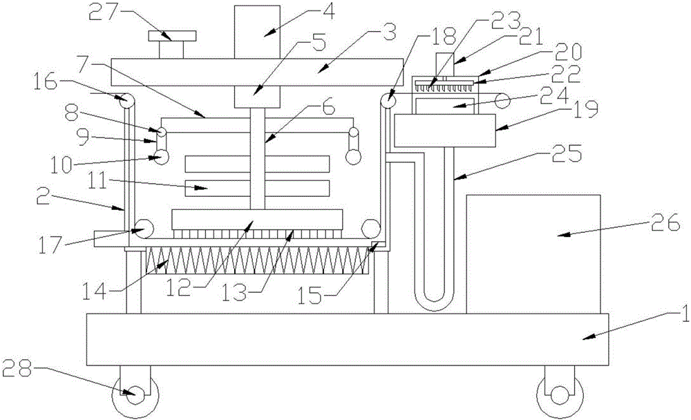
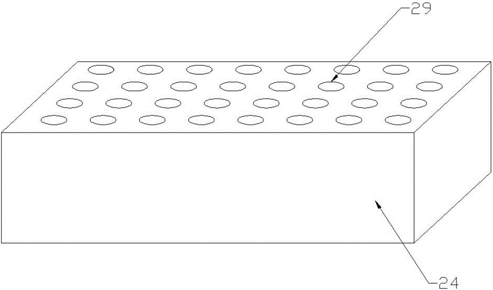
[0015] Please refer to the figure, in the embodiment of the present invention, a high-efficiency dewatering dyeing machine includes a base 1, a dyeing vat 2, an upper cover 3 and a motor 4; rollers 28 are installed on the underside of the base 1 to move the dyeing machine Convenient and flexible to use, the dyeing vat 2 is fixed on the base 1, the top of the dyeing vat 2 is covered with an upper cover 3, and the upper cover 3 is connected to the dyeing vat 2 th...


PUM

PropertyMeasurementUnit
lengthaaaaaaaaaa

Abstract

The invention discloses a high-efficient dewatering dyeing machine, comprising a base, a dye vat, an upper cover and a motor; the output shaft of the motor is connected with a reducer, and the middle lower output end of the reducer is fixedly connected with a vertical rotary shaft; the lower end of the rotary shaft is fixed with a horizontal brush disk, and the lower surface of the brush disk is provided with several brushes; stirring blades are fixed on the rotary shaft, and both sides of the rotary shaft are further provided with horizontal hammering rods, hinges are installed on both ends of the hammering rods; link rods are installed on the hinges, and hammers are fixed on the tail end of the link rods; a U-shaped pipe is connected to the side wall of the dye vat, and interconnected with a collecting tank. Through a guide roller, cloth is conveyed from the dye vet internally, and the motor drives the hammer to rotate and strikes on the cloth, thus the cloth is continuously vibrated so that the dye is contacted with the cloth; the cloth is dyed evenly by cooperating with the lower part; fluid on the conveyed cloth is scrapped through a scraper plate, and then delivered to the dye vat again, thus the loss of dye fluid is reduced.

Description

technical field [0001] The invention relates to a textile dyeing machine, in particular to a high-efficiency water-removing dyeing machine. Background technique [0002] In the process of dyeing cloth, the traditional method is to manually put the cloth into the dye vat, and then manually drag the other end of the cloth slowly for dip-dyeing. People directly contact with the dye, which is easy to stain the clothes. The dye contains many harmful substances. , it is easy to damage the health of workers, and the manual operation cannot evenly control the time of dyeing. Due to the inconsistent speed of different workers, the quality of the dyed cloth is not the same, and the dyeing is uneven, which affects the quality of the whole batch of cloth; To take out the dyeing vat, the dyeing water on the cloth needs to be manually wrung out, and the work efficiency is low, which affects the health of the workers. Contents of the invention [0003] The purpose of the present inventi...

Claims


Application Information

Patent Timeline
Patent Type & Authority Applications(China)
IPC IPC(8): D06B3/20D06B13/00D06B23/20D06B23/22D06B15/08
CPCD06B3/206D06B13/00D06B15/085D06B23/20D06B23/22D06B2700/09D06B2700/36
Inventor 不公告发明人
Owner ZHENGZHOU TIANSHUN ELECTRONICS TECH CO LTD
Why Eureka
Try Eureka