A kind of firmly connected scaffold top support
A scaffolding and top bracing technology, which is applied to the accessories of scaffolding, buildings, and housing structure supports, etc., which can solve problems such as prone to collapse and weak connections
Active Publication Date: 2018-09-14
广东九为工程安全科技股份有限公司
View PDF7 Cites 0 Cited by
- Summary
- Abstract
- Description
- Claims
- Application Information
AI Technical Summary
Problems solved by technology
[0002] At present, the top support used in the erection of formwork scaffolding is prone to the danger of collapse due to its weak connection with the scaffolding riser
Method used
View moreImage
Smart ImageViewing Examples
Examples
Embodiment Construction
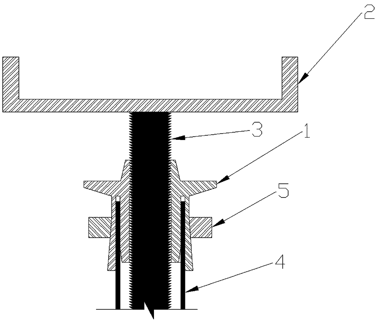
[0010] Summary of the Invention The specific implementation of the present invention has been described in detail and will not be repeated here. It should be explained that the outer coarse thread of the screw 3 and the inner coarse thread of the clamp 1 cooperate with each other to make the clamp 1 move up and down along the screw 3 relatively quickly.
Login to View More PUM
 Abstract
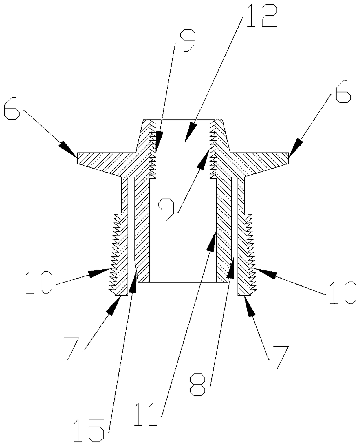
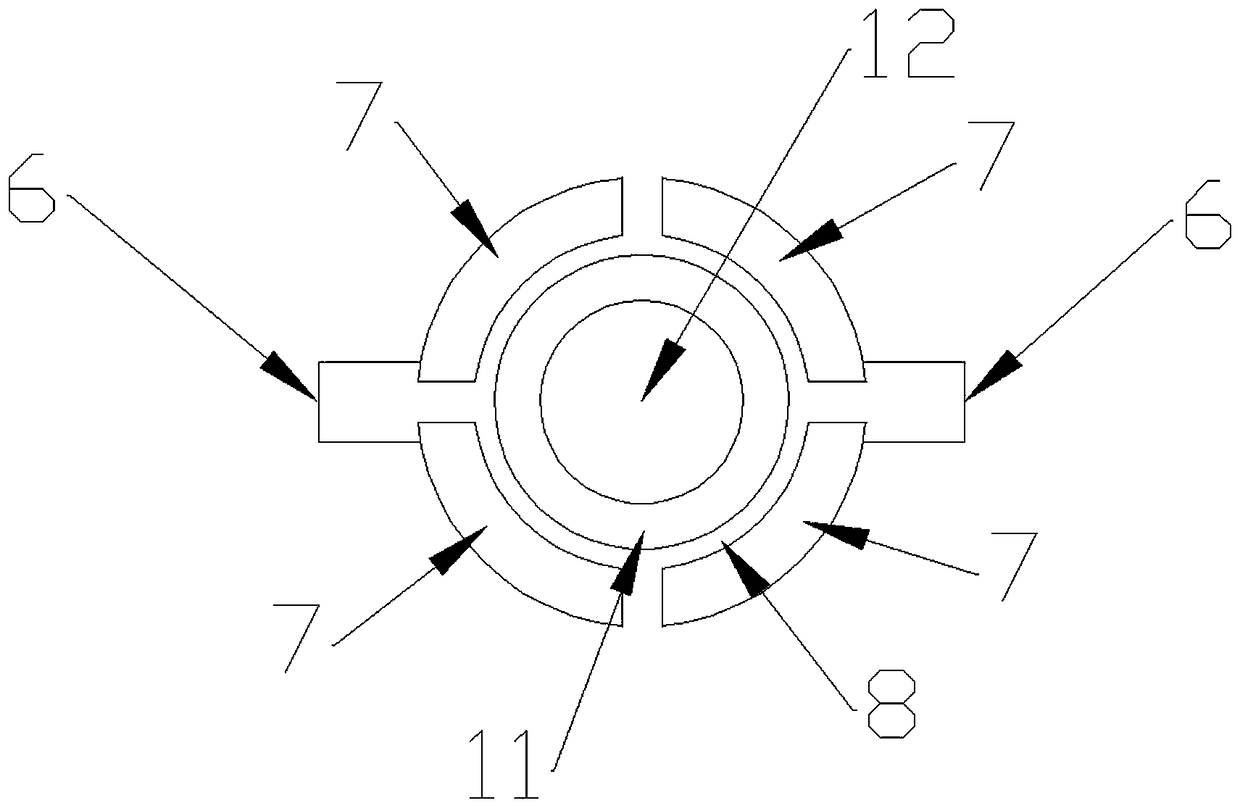
The invention relates to a scaffold dead shore capable of achieving firm connection which is used for building a template scaffold in the field of constructional engineering. The scaffold dead shore can be firmly connected to a scaffold vertical tube, and then scaffold collapse can be avoided. The scaffold dead shore includes a clamp 1, a support plate 2, a screw 3 and a nut 5. The main working principle of the scaffold dead shore includes: rotating the clamp 1 along the screw 3 to a preset height from bottom to top; inserting the lower end of the screw 3 into the upper end of a steel tube 4; clamping the upper end of the steel tube 4 into a circular groove 8 of the clamp 1; screwing the nut 5 downward, wherein clamp sheets 7 are cone-shaped arc sheets with large upper ends and small lower ends, when the nut 5 is screwed downward, the plurality of clamp sheets 7 can rotate inward to tightly clamp the steel tube 4; and when the clamp 1 needs to be taken out, the nut 5 is unscrewed upward, the clamp sheets 7 reset elastically, the steel tube 4 is released, a hammer is used to knock on a knock ear 6 of the clamp 1 counter-clockwise, the clamp 1 is rotated along the screw 3 counter-clockwise, the upper end of the steel tube 4 goes out of the circular groove 8 of the clamp 1, and the clamp 1 and the screw 3 can be taken out.
Description
technical field [0001] The invention is mainly used for setting up formwork and scaffolding in the field of construction engineering. Background technique [0002] At present, the top support used for setting up formwork scaffolding is prone to the risk of collapse because it is not firmly connected with the standpipe of the scaffolding. Contents of the invention [0003] The present invention solves the above-mentioned problems, and it is firmly connected with the standpipe of the scaffold, and the danger of scaffold collapse will not occur; it is mainly composed of clamps (1), braces (2), screw rods (3), and nuts (5); the clamps ( 1) It is mainly composed of knocking ears (6), multiple clips (7), annular groove (8), and inner cylinder (11). The left and right sides of the inner cylinder (11) are fixed with knocking ears (6), and the inner cylinder ( The inner wall of 11) has internal coarse threads (9), and the threads of the internal coarse threads (9) and the threads ...
Claims
Login to View More Application Information
Patent Timeline
 Patent Type & Authority Patents(China)
IPC IPC(8): E04G5/00
CPCE04G5/00
Inventor 彭宝安
Owner 广东九为工程安全科技股份有限公司
Features
- R&D
- Intellectual Property
- Life Sciences
- Materials
- Tech Scout
- Unparalleled Data Quality
- Higher Quality Content
- 60% Fewer Hallucinations
Learn More Browse by: Latest US Patents, China's latest patents, Technical Efficacy Thesaurus, Application Domain, Technology Topic, Popular Technical Reports.
© 2025 PatSnap. All rights reserved.Legal|Privacy policy|Modern Slavery Act Transparency Statement|Sitemap|About US| Contact US: help@patsnap.com


