
Mobile sliding rail pushing type automatic side slope drilling device

A drilling device and propulsion technology, which are applied to supporting devices, drilling equipment and methods, drilling equipment, etc., can solve the problems of inconvenient movement, high labor intensity, waste of construction, etc., and achieve improved position accuracy, energy saving, location precise effect

Inactive Publication Date: 2017-03-22
中交二公局第四工程有限公司
View PDF10 Cites 6 Cited by
  • Summary
  • Abstract
  • Description
  • Claims
  • Application Information

AI Technical Summary

Problems solved by technology

[0003] At present, the main application of rock drilling on the slope is to build scaffolding around the slope, and then drill holes one by one on the scaffolding. Therefore, a lot of materials are needed to build the scaffolding, which is not only wasteful but also difficult to construct. Uphill operations have disadvantages such as inconvenient movement, high labor intensity, and danger. Therefore, it is an urgent need to design and produce a device that is convenient for drilling operations on slopes.

Method used


Image

  • Mobile sliding rail pushing type automatic side slope drilling device
  • Mobile sliding rail pushing type automatic side slope drilling device
  • Mobile sliding rail pushing type automatic side slope drilling device

Examples


Embodiment Construction

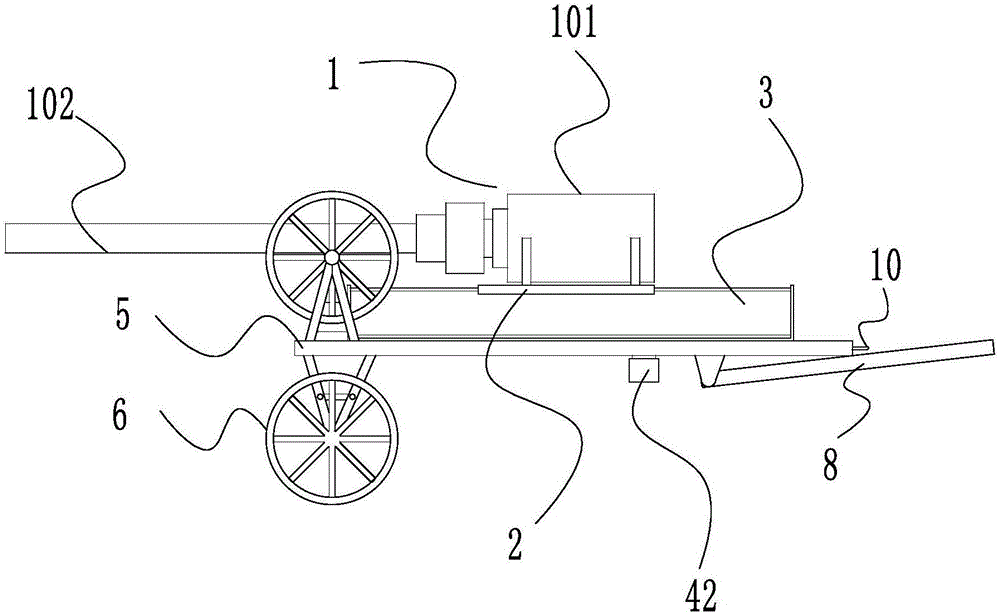
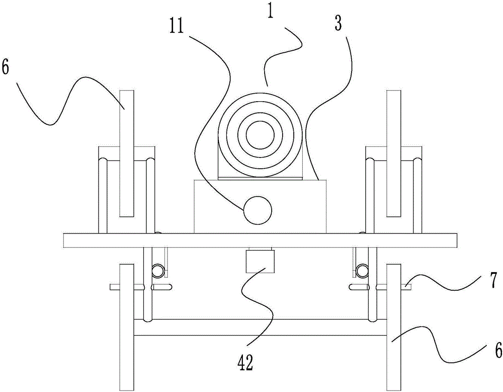
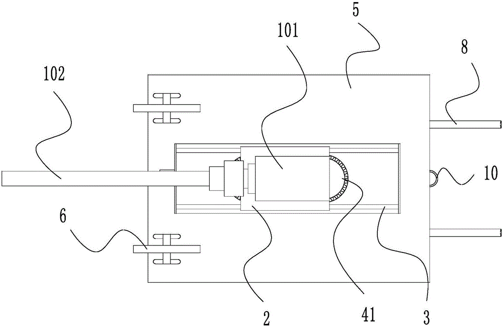
[0028] like figure 1 , the present invention includes a drilling machine 1, and the drilling machine 1 is driven by a drilling motor 101 to rotate a drill rod 102 to achieve drilling. In order to better understand the present invention, the implementation of the present invention will be explained in detail below in conjunction with the accompanying drawings.

[0029] like Figure 2 to Figure 9 As shown, the drilling motor is fixedly installed on the slide plate 2, the slide plate 2 is a flat plate with a chute, the slide plate 2 is installed on the track plate 3 vertically placed on the lower side, and the track plates 3 are four The vertical plate welding of rectangular distribution is formed, and described track plate 3 is provided with the slide rail that cooperates with slide plate 2, and described slide plate 2 is connected with pushing mechanism 4, and pushing mechanism 4 can push slide plate 2 to slide left and right along track plate 3;

[0030] The lower end of the ...


PUM


Abstract

The invention discloses a mobile sliding rail pushing type automatic side slope drilling device which comprises a drilling machine, wherein the drilling machine drives a drilling rod to rotate through a drilling motor to realize perforation; the drilling motor is fixedly mounted on a sliding plate; the sliding plate is a flat plate with a sliding chute; the sliding plate is mounted on a rail plate vertically arranged on the lower side; the rail plate is formed by welding four vertical flat plates distributed in a rectangular manner; sliding rails matched with the sliding plate are arranged on the rail plate; the sliding plate is connected with a pushing mechanism; the pushing mechanism can push the sliding plate to slide left and right along the rail plate; the lower end of the rail plate is fixed on a platform; two wheels are respectively arranged on the upper and lower sides of the left end of the platform; the wheels are mounted on the platform through rotating shafts and bearings. When a side slope is drilled, the drilling machine can be conveniently perpendicular to the side slope and positions can be changed freely, so that the waste of resources due to operation via installation of a scaffold is avoided.

Description

technical field [0001] The invention relates to a side slope operation device, in particular to a movable sliding rail propelling type side slope automatic drilling device. Background technique [0002] Slope is the most common form in road engineering. With the rapid development of my country's economy and the increasing emphasis on environmental protection, the requirements for road slopes are getting higher and higher. In order to prevent the instability of the road slope, which will bring huge economic losses to the country and endanger the safety of people's lives and property, the layout should be rationalized, and practical, reasonable, economical and beautiful engineering measures should be selected according to local conditions to ensure the stability of the road and the safety of high-speed driving. At the same time, it has the effect of coordinating with the surrounding environment, maintaining the relative balance of the ecological environment and beautifying the...

Claims


Application Information

Patent Timeline
Patent Type & Authority Applications(China)
IPC IPC(8): E21B7/02E21B7/04E21B15/04
CPCE21B7/024E21B7/026E21B7/04E21B15/003E21B15/04
Inventor 杨善成吕国仁金国鹏贺正伟谢鑫周洪军
Owner 中交二公局第四工程有限公司
Learn More