
Multi-connection system and control method for subcooling circuit valve body thereof

A technology of a multi-connected system and control method, applied in the field of multi-connected systems, can solve the problems of poor cooling effect, gas leakage, large valve body, etc., and achieve the effects of low exhaust temperature, good cooling effect, and high energy efficiency.

Active Publication Date: 2019-04-30
GD MIDEA HEATING & VENTILATING EQUIP CO LTD +1
View PDF6 Cites 0 Cited by
  • Summary
  • Abstract
  • Description
  • Claims
  • Application Information

AI Technical Summary

Problems solved by technology

[0003] For the existing multi-connected products, under the same box appearance, the heat exchanger and valve body of the subcooling circuit are selected for the model with the largest cooling capacity of the box. However, different cooling capacities The nominal box body requires different flow rates of the subcooling circuit, which leads to the fact that the valve body selected for the maximum cooling capacity is too large for other models with small cooling capacity
If the valve body is mistakenly opened to the maximum opening when controlling the valve body, for the model with a small cooling capacity, the deterioration ratio of the cooling capacity will reach the maximum. The cooling effect becomes worse
[0004] Moreover, when the outdoor temperature and indoor temperature are both high, the subcooling degree from the outdoor unit into the distribution device is very low (or even no subcooling degree), and the subcooling circuit will run out of air. At this time, the system will follow the The superheat controls the valve body, and the valve body is opened to the maximum by mistake, resulting in more serious air loss, and the system has no supercooling effect

Method used


Image

  • Multi-connection system and control method for subcooling circuit valve body thereof
  • Multi-connection system and control method for subcooling circuit valve body thereof

Examples


Embodiment Construction

[0024] Embodiments of the present invention are described in detail below, examples of which are shown in the drawings, wherein the same or similar reference numerals designate the same or similar elements or elements having the same or similar functions throughout. The embodiments described below by referring to the figures are exemplary and are intended to explain the present invention and should not be construed as limiting the present invention.

[0025] The method for controlling the subcooling circuit valve body in the multi-line system and the multi-line system according to the embodiments of the present invention will be described below with reference to the accompanying drawings.

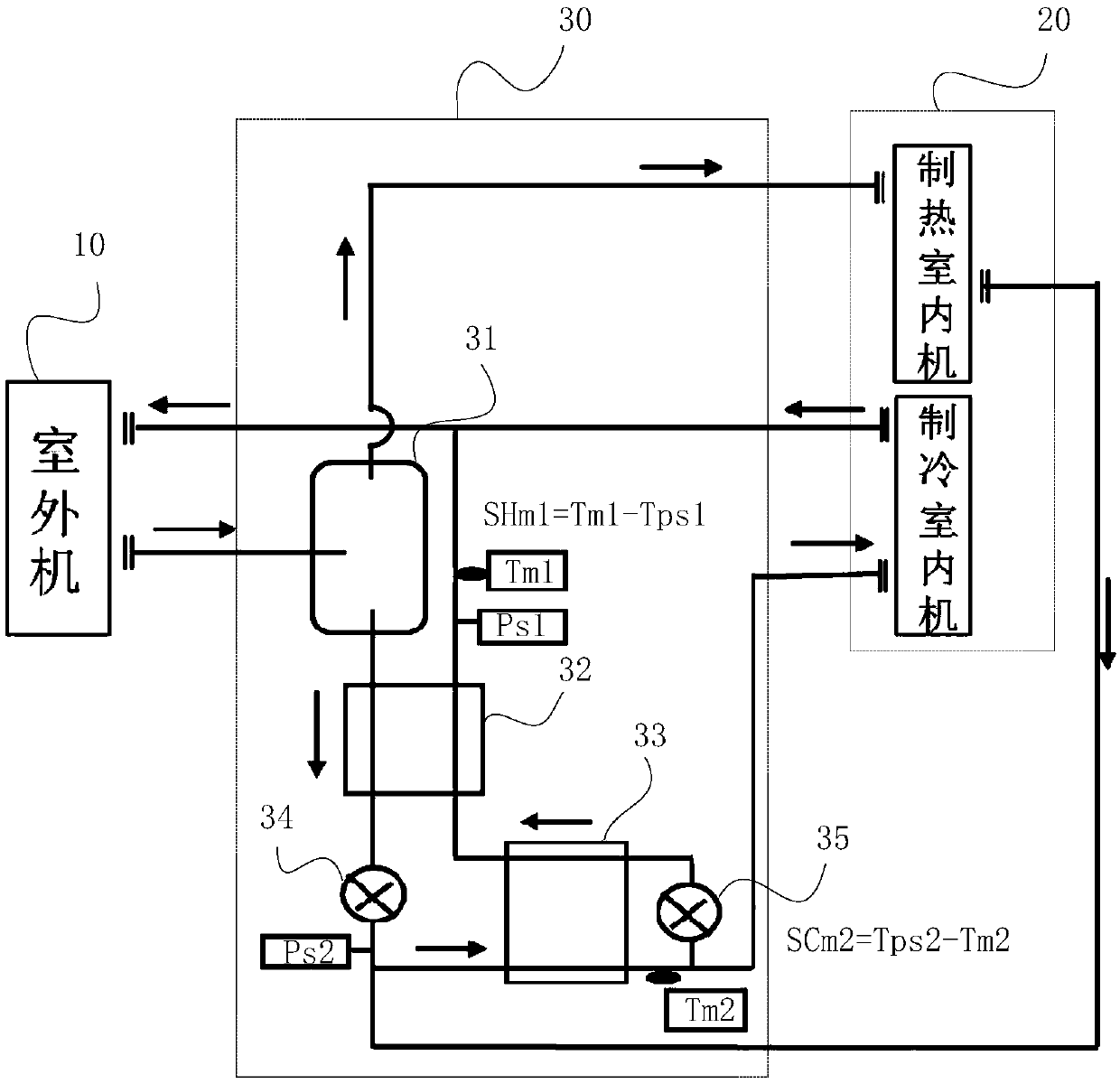
[0026] figure 1 is a schematic structural diagram of a multi-line system according to an embodiment of the present invention. Such as figure 1 As shown, the multi-split system may include an outdoor unit 10, a plurality of indoor units 20, a distribution device 30 and a control device (no...


PUM


Abstract

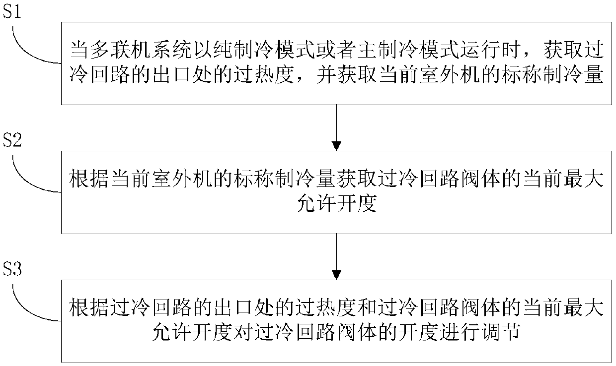
The invention discloses a multiple-on-line system and a control method for a super-cooled loop valve body of the multiple-on-line system. The multiple-on-line system comprises an outdoor unit, a plurality of indoor units and a flow-splitting device, wherein the flow-splitting device comprises a super-cooled loop and a super-cooled loop valve body which is arranged at an inlet of the super-cooled loop. The method comprises the following steps of: obtaining degree of superheat at an outlet of the super-cooled loop and obtaining nominal refrigerating capacity of the existing outdoor unit when the multiple-on-line system operates in a pure refrigerating mode or a main refrigerating mode; obtaining existing maximum allowable opening degree of the super-cooled loop valve body according to the nominal refrigerating capacity of the existing outdoor unit; and regulating the opening degree of the super-cooled loop valve body according to the degree of superheat at the outlet of the super-cooled loop and the existing maximum allowable opening degree of the super-cooled loop valve body. According to the multiple-on-line system and the control method for the super-cooled loop valve body of the multiple-on-line system disclosed by the invention, maximum opening degree of the super-cooled loop valve body is limited, and the super-cooled loop is prevented from gas release when the opening degree of the valve body is too large, so that the system can obtain a relatively low gas exhaust temperature and relatively good refrigerating effect, and therefore, energy efficiency is relatively high.

Description

technical field [0001] The invention relates to the technical field of air conditioning, in particular to a method for controlling a subcooling circuit valve body in a multi-connection system and a multi-connection system. Background technique [0002] The multi-connected system has four modes: pure cooling, pure heating, main cooling and main heating. Among them, the main cooling mode and main heating mode can use the condensation heat and evaporation heat of the system at the same time, which greatly improves the energy efficiency of the system. The outdoor unit distributes the gas-liquid refrigerant to the indoor units with different cooling and heating requirements through the distribution device. The sub-cooling circuit is set in the distribution device, and two heat exchangers in series are used as sub-coolers. [0003] For existing multi-connected products, under the same box appearance, the heat exchanger and valve body of the subcooling circuit are all selected for ...

Claims


Application Information

Patent Timeline
Patent Type & Authority Patents(China)
IPC IPC(8): F24F3/06F24F11/84
CPCF24F3/065F24F11/83F24F11/84
Inventor 李元阳谭志军
Owner GD MIDEA HEATING & VENTILATING EQUIP CO LTD
Learn More