Dehydration device for natural gas

A dehydration device and natural gas technology, applied in the direction of gas fuel, dispersed particle filtration, petroleum industry, etc., can solve the problems of inability to dehydrate and low dehydration efficiency, and achieve the effect of preventing waste, preventing dirt from clogging, and ensuring long-term effective sealing

Active Publication Date: 2015-11-25
PETROCHINA CO LTD
View PDF6 Cites 9 Cited by
  • Summary
  • Abstract
  • Description
  • Claims
  • Application Information

AI Technical Summary

Problems solved by technology

[0005] The purpose of the present invention is to provide a natural gas dehydration device to solve the defects of th

Method used


Image

  • Dehydration device for natural gas
  • Dehydration device for natural gas
  • Dehydration device for natural gas

Examples


Example Embodiment

[0040] In order to have a clearer understanding of the technical features, objectives and effects of the present invention, specific embodiments of the present invention will now be described with reference to the accompanying drawings.

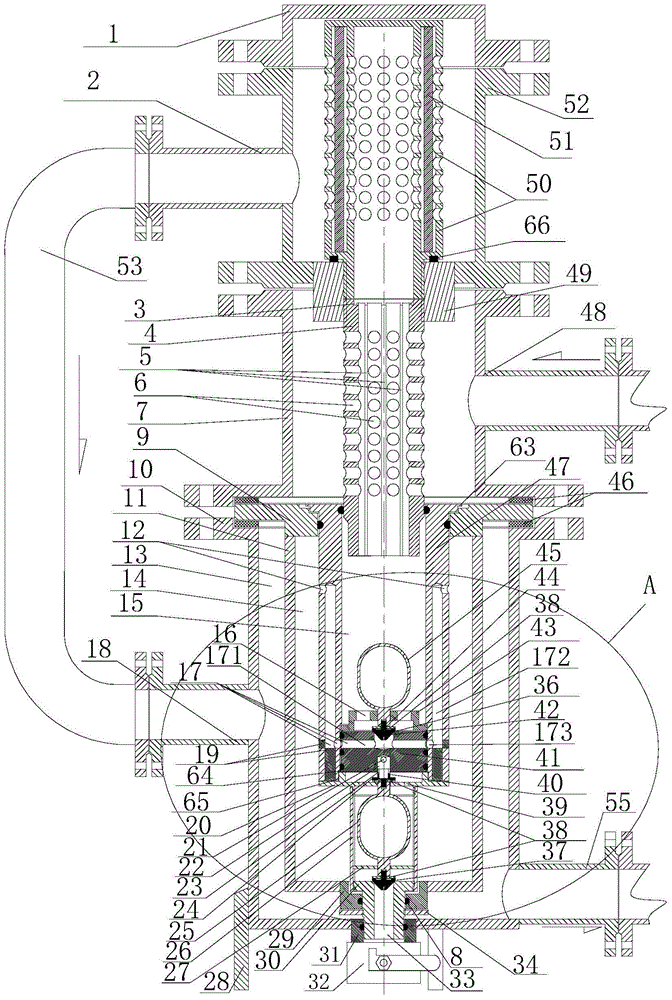
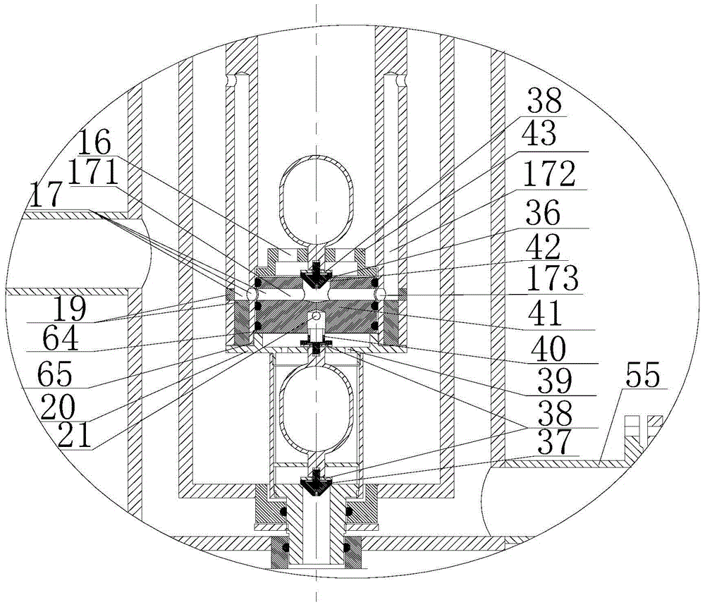
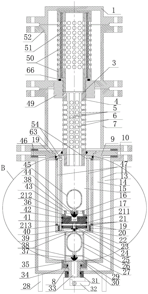
[0041] Such as Figure 1 to Figure 4 As shown, the present invention provides a natural gas dehydration device for dehydration treatment of wet natural gas, where wet natural gas or wet gas refers to natural gas containing water vapor, or in an oil production station, it can easily reduce the temperature when the temperature is below zero. The natural gas that can produce freezing in the pipeline is called wet natural gas or wet gas, and the natural gas that does not freeze is called dry natural gas or dry gas. The natural gas dehydration device includes a dehydration part for dehydration and a drainage part for drainage.

[0042] Wherein, the dehydration part includes a first cylinder body 7 and a second cylinder body 52 sealed and connected abov...


PUM


Abstract

The invention provides a dehydration device for natural gas. The dehydration device comprises a dehydration part and a drainage part, wherein the dehydration part comprises a first cylinder and a second cylinder, a wet gas inlet is formed in the side wall of the first cylinder, a gas-water guide pipe is arranged in the first cylinder in a penetrating manner, and a gas passing hole communicated with the wet gas inlet penetrates through the side wall of the gas-water guide pipe; the second cylinder is connected above the first cylinder in a sealed manner, a cylindrical water filter film is arranged in the second cylinder, an inner cavity of the water filter film is communicated with the gas-water guide pipe, and a first dry gas outlet is formed in the side wall of the second cylinder; the drainage part comprises a water-gas shunt pipe, the upper end of the water-gas shunt pipe is connected with the lower end of the gas-water guide pipe in a sealed manner, the lower end of the water-gas shunt pipe is connected with an upper valve, a water containing chamber is arranged in the water-gas shunt pipe, and an upper floating ball is arranged at the lower part of the water containing chamber and connected with the upper valve. The water filter film is used for filtering and dehydrating wet natural gas, the defect that dehydration cannot be effectively performed at the high air temperature in the prior art is overcome, and automatic dehydration and automatic drainage are realized around the clock all the year round.

Description

technical field [0001] The invention relates to a dehydration device, in particular to a natural gas dehydration device used for dehydration of self-produced natural gas in an oil production station. Background technique [0002] In the process of oil field development, the natural gas separated from the buffer tank of the oil production station is transported to the water jacket furnace area of ​​the oil production station through the natural gas pipeline network, and is used for the heating furnace, the export furnace, the oil mixing furnace, the water mixing furnace, and the primary heating furnace. For heating gas, if the gas production is greater than the water jacket furnace consumption of the oil production station, the excess will be sent to the external gas transmission trunk line for other uses. Because the natural gas separated by the buffer tank of the oil production station contains a certain amount of water (the buffer tank of the oil production station has no ...

Claims


Application Information

Patent Timeline
IPC IPC(8): C10L3/10B01D46/54
Inventor 陈伟东杨波刘长芝赵光明张长胜
Owner PETROCHINA CO LTD
Why Eureka
Try Eureka